TPS-1 User’s Manual: Hardware 8. PROFINET IO switch
R19UH0081ED0107 Rev. 1.07 page 54 of 86
Jul 30, 2018
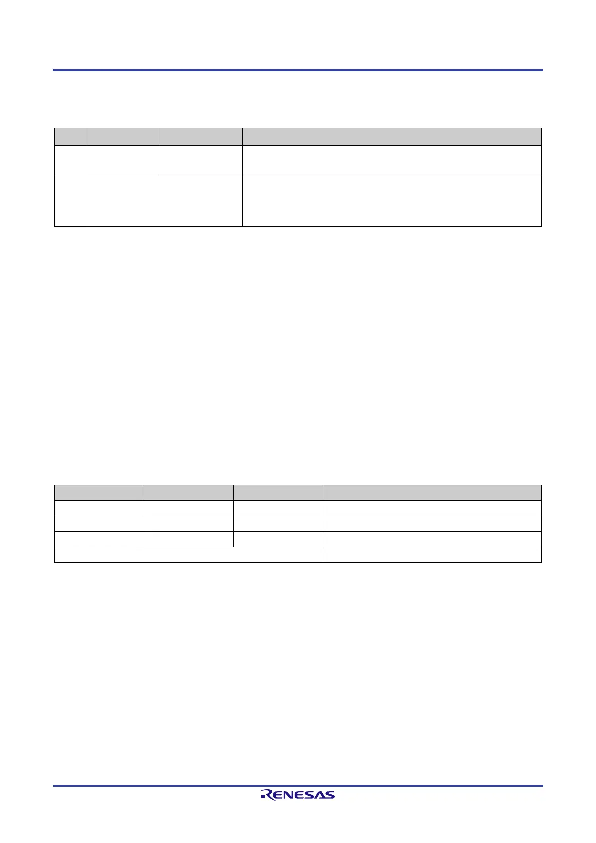
8.4. Additional TPS-1 pins
The pins ATP and EXTRES are used for PHY1 and PHY2.
Table 8-7: Additional TPS-1 pins
Pin Designation I/O Description
H12 ATP AI/O (analog
I/O)
Analog Test:
This signal is used for the manufacturing process. Pin is left open.
I/O)
Connect via a resistor 12.4KΏ / 1% to GND. This external resistor
should be placed as close as possible to the chip. It must be
terminated to analog GND.
8.5. Integrated voltage regulator 1.5 V
The integrated PHY components require a supply voltage of 3.3 V and 1.5 V. The supply voltage 1.5 V is supported by an internal voltage regulator.
For a correct operation, some additional electronic components are necessary. Figure 8-2: Internal voltage regulator shows the design of the switching
regulator.
During normal operation (Switching Regulator is running and POR is active), the pins TEST1, TEST2, and TEST3 are connected to GND via a pull-
down resistor.
It is also possible to feed the TPS-1 with an external voltage of 1.5 V. Then you have to switch off the regulator (Pin TEST1 set to 1 with a pull-up).
The regulator output (Pin LX) changes to HiZ status.
The POR function must be in operation because this signal is used in combination with the external signal RESETN to enable the TPS-1 dies.
Caution: The 3.3 V supply voltage has to be connected to BVDD (pin J1) and AVDD_REG (pin F2). AVDD_REG is used
to generate the internal POR signal of the TPS-1. If you are not using the internal regulator the pin AVDD_REG
has also been connected to 3.3 V to prevent reset blocking.
The other combinations of the signals TEST1, TEST2 and TEST3 are used for the chip test at the factory process.
The switching regulator is designed to supply the PHY components. It is not allowed to connect additional components. You will find a
recommendation for the circuitry of the switching regulator in the Chapter “Board Design Information, Switching Regulator”.
Table 8-8 describes the different modes of the switching regulator.
Table 8-8: Switching regulator operating modes
0 0 0 Normal mode: Regulator and POR on.
Only POR mode: Regulator off, POR on.
0 1 0 Regulator and POR circuitry switched off (Note).
Other options reserved for test
Note: This combination should be avoided, because you set the TPS-1 permanently into the reset state.
 Loading...