TPS-1 User’s Manual: Hardware 4. Shared memory structure
R19UH0081ED0107 Rev. 1.07 page 35 of 86
Jul 30, 2018
The structure of the configuration written into the NRT area is checked by the TPS-1 firmware. If there are structure errors the TPS-1 firmware does not
start.
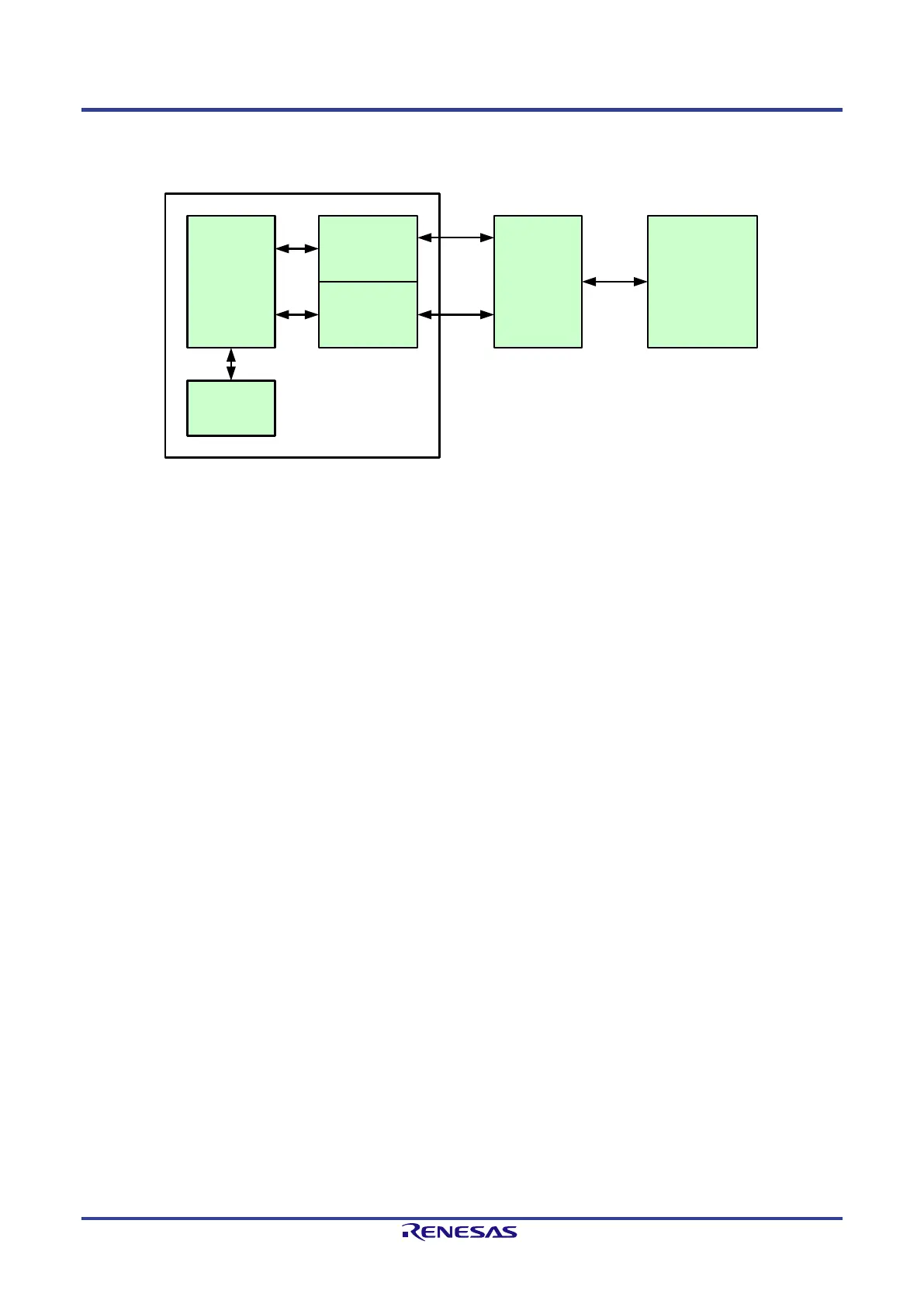
The host interface and the NRT area are accessible in a continuous address space.
TPS-1
PROFINET
STACK
NRT-Area
Input / Output
Area
RT-DATA
Access
Library
Host
parallel
or serial
access
SWITCH
Figure 4-2: General overview host interface
Access to the NRT area and Input/Output area is processed with the support of a software library. The memory area (shared memory) is used for the
access to acyclic and cyclic data. The size depends on the device.
Exchange of the cyclic data is managed in the peripheral interface (input / output area). The structure of this area is fixed. It is possible to manage one
AR (Application Relations) in the first release.
• one I-Data-CR
• one O-Data CR
The IO data has a maximum size of 1016 Byte (cyclic data), dynamically distributed to two ARs.
Note
Note: A maximum data size of 1016 Byte is possible with stack version 1.4.0.14 or newer. This data size can be flexibly distributed over 2
PROFINET application relations (example: one AR uses 256 Bytes, the other AR uses 760 Bytes). With stack versions earlier than 1.4.0.14
the maximum data size is limited to 340 Bytes for each of the two configurable application relations.
 Loading...