25
Installation (continued)
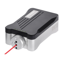
Pneumatic connection
Connect the two standard and one optional
Ø4.0mm (0.16 in) air pipes to the connectors on
the back of the unit (see “Installation” diagram on
page 23).
Both pneumatic connectors on the APCS (Port 1
and 3) must be connected with pipe. For APCS
with no “air bleed” Port 1 must be connected to an
exhaust/breather line routed to a clean isolated
area away from any electrical connections. An
exhaust silencer/lter is recommended.
Electrical connection
Connect the M12 connector to the mating
cable (not supplied). For more information see
“Connecting the APC to an HSI interface and the
CNC” on page 10 or “Connecting the APC to an
HSI-C interface and the CNC” on page 11 and
“Retract conrm sensor” on page 12.
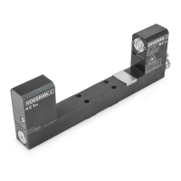
Mounting the APC to the machine
1. Mount the APC to tting location using
4×M4 screws (supplied). Leave the screws
semi-tight.
2. Set the APC base perpendicular to the
mounting face. The gap will be approximately
1mm (0.04 in). Torque all four screws to
between 2.60Nm and 2.70 Nm (1.92 lbf.ft
and 1.99 lbf.ft).

 Loading...