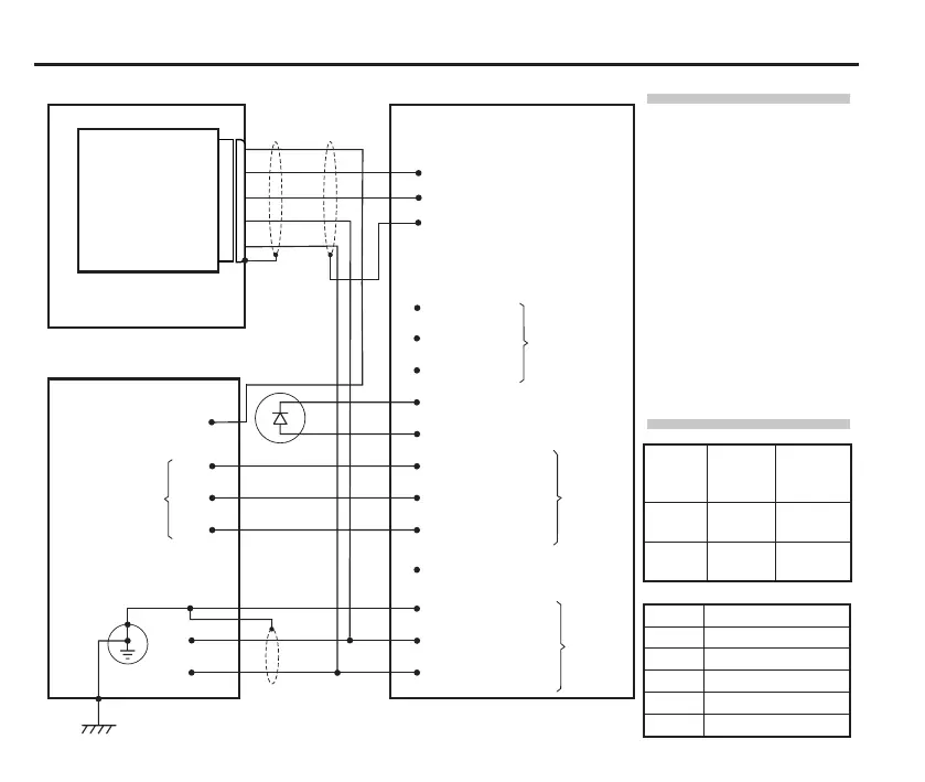
10 Connecting the APC to an HSI interface and the CNC
Controller connector (12-way)
1 0 V
2 Inhibit return
4 External LED 0 V
5 External LED 10 V
6 NO
7 Common
10 Screen
11 Supply 0 V
12 Supply 12 V – 30 V
8 NC
Power
input
9 12 V – 30 V out (fused 100 mA)
3 Inhibit
Standard probe connector (3-way)
1 Probe Input +
2 Probe Input –
3 Screen
CNC
Probe
input
Controller protective earth
(also referred to as PE star
point or earth plate)
Screen
0 Vdc
12 Vdc – 30 Vdc
Controller reference ground
HSI interface
Machine tool
APC
Status Normally
open
(NO)
Normally
closed
(NC)
Probe
triggered
Closed Open
Probe
seated
Open Closed
NOTES:
When the APC is not being used,
it is recommended that the inhibit
function is enabled. The retract
conrm output could be used to
set the inhibit function (for more
information see “Probe inhibit
function” on page 12).
When connecting the APC to the
HSI interface, use the connection
labelled STANDARD PROBE.
Connect either pin 6 or pin 8, but
do not connect both wires.
Status
output
SSR
2
4
1
5
3
Pin APC connections
2 Retract conrm sensor
4 Probe input +
1 Probe input –
5 Supply 0 V
3 Supply 12 V – 30 V
Retract conrm input
Probe inhibit
function

 Loading...