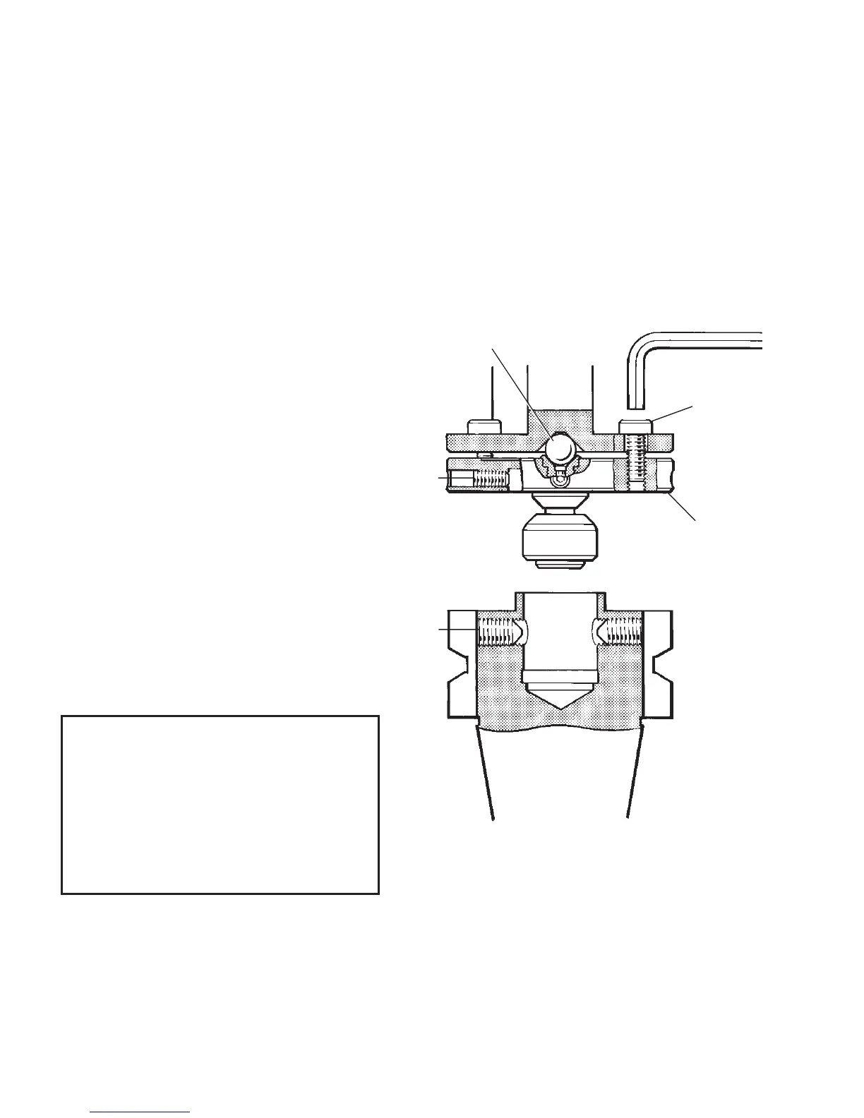
Ø8 mm
ball
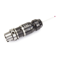
SHANK
PROBE
B
C
A
Adjusting plate
1-19
Note :
1. DURING ADJUSTMENT CARE SHOULD
BE TAKEN NOT TO ROTATE THE PROBE
RELATIVE TO THE SHANK.
2. IF A PROBE/SHANK UNIT IS
ACCIDENTALLY DROPPED, IT SHOULD
BE CHECKED FOR ON-CENTRE
POSITION.
3. DO NOT HIT OR TAP THE PROBE TO
ACHIEVE ON-CENTRE ADJUSTMENT.
Stage 1 Probe/shank mounting
1. Remove the battery covers and battery
- see page 1-13. Then remove the adjusting
plate from the probe body.
2. Refit the adjusting plate onto the probe
body, with the Ø8 mm centre ball
located between the adjusting plate
and probe. Tighten fixing screws A lightly
using special 4 mm AF hexagon key
(supplied in toolkit).
3. Fully slacken screws B.
4. Grease screws C, and fit into shank.
5. Fit the probe with adjusting plate and ball
onto the shank and visually position the
probe centrally relative to the shank.
Partially tighten, screws C to 2 - 3 Nm
(1.47 - 2.2 lbf.ft)
6. Mount the probe/shank assembly into
the machine spindle.
PROBE/SHANK MOUNTING WITH ADJUSTING PLATE + CENTRE BALL
Special 4 mm AF
short arm
hexagon key