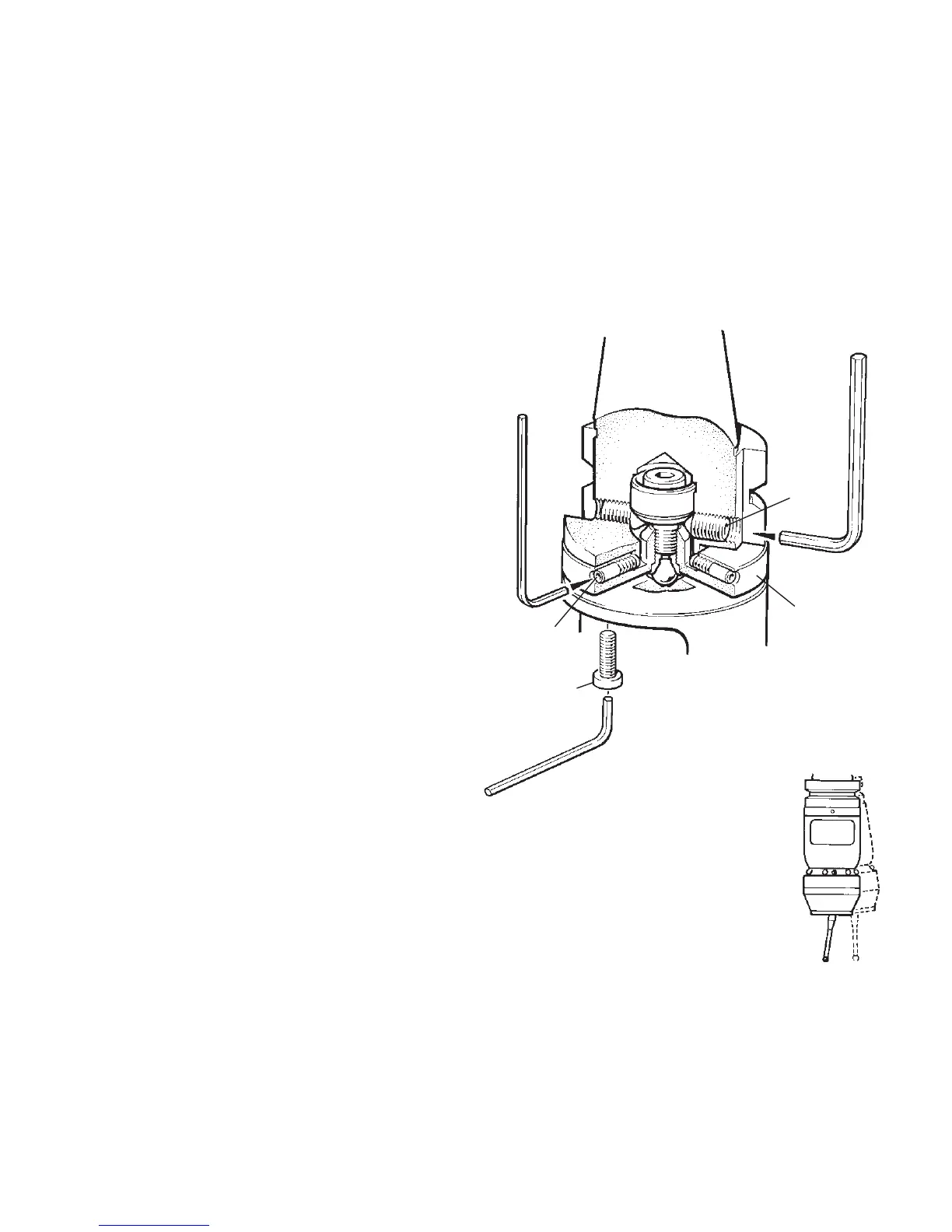
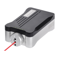
2.5 mm AF
Adjusting
plate
B
A
C
4 mm AF
PROBE
SHANK
1-20
Stage 2 On-centre adjustment
7. Check the stylus for vertical alignment
relative to the bore hole. Adjust screws A
if alignment is required, and then fully
tighten screws A to 5.1 Nm (3.76 lbf.ft).
8. Each of the four screws B will move the
probe relative to the shank, in the X or Y
direction as pressure is applied.
Tighten individually, backing off after
each movement.
9. When the stylus tip run-out is less than
20 µm,
fully tighten screws C to 6 - 8 Nm
(4.4 - 5.9 lbf.ft).
10. For final centering use screws B to move
the probe, progressively slackening on one
side and tightening the opposite screw,
as
the final setting is approached, using two
hexagon keys.
Tip run out of 5 µm (0.0002 in) should
be achievable.
11. It is important that all four screws B are tight
or tightened to 1.5 - 3.5 Nm (1.1 - 2.6 lbf.ft)
once the final setting has been achieved.
12. When on-centre adjustment is completed,
replace battery and covers - see page 1-13.
Special 4 mm
AF
short arm
hexagon key
STYLUS ON-CENTRE ADJUSTMENT WITH ADJUSTING PLATE + CENTRE BALL