en
Fixscreen
®
100 Slim (F)
40
In case the power supply is taken from indoors, drill a hole of 10 mm, to gain access inside the
building/construction, in function of location of cable feed (B, F, H, N, W, & V).
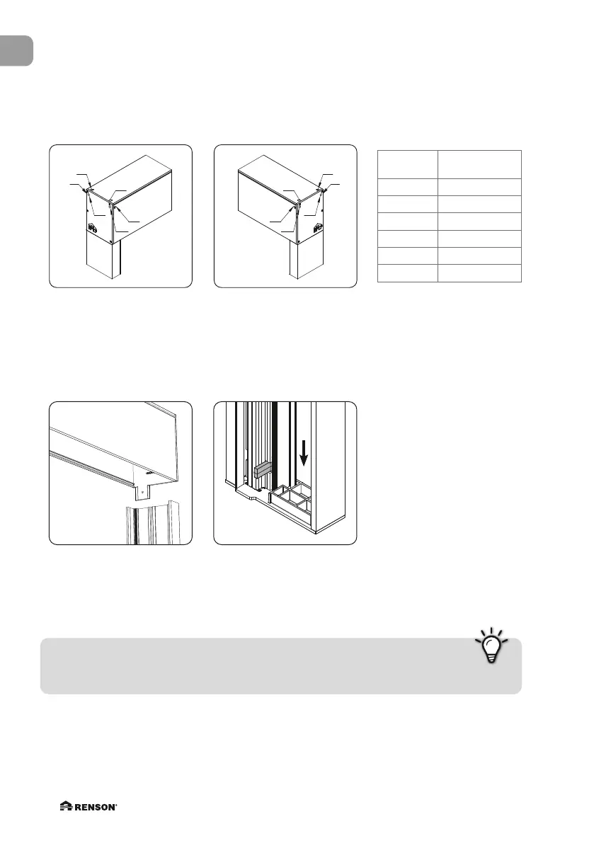
3.3 • Installation of the head box
3.3.1 • Cable feed
3.3.2 • Fixation of the head box
LF
LV
LH
LW
LN
RF
RV
RB
RH
RW
RN
LF
LV
LB
LH
LW
LN
RF
RV
RB
RH
RW
RN
110
35
48
35
48
58
Fertige Höhe
Finished height
Hauteur finie
Afgewerkte hoogte
RF
RV
RB
RH
RW
RN
LF
LV
LB
LH
LW
LN
RF
RV
RB
RH
RW
RN
110
35
48
35
48
58
Fertige Höhe
Finished height
Hauteur finie
Afgewerkte hoogte
LEFT RIGHT
Cable feed
Position cable
feed
B back
F top
H sideways
N front
V top
W sideways
Place the empty head box on
the fixed profile of the side
guiding channels.
Respect the position of the
side guiding channel. The
(black) clicker
➄
is at the
bottom of the side guiding
channel.
Tip:
After placing the head box on the fixed profile of the side guiding channel, make sure
it is straight using the spirit level before proceeding.