41
42
Control Panel
12V DC 500mA
850 / 900 / 1800 / 1900MHz
≤ 110mA
≤ 340mA
Lithium-Ion batter y 3,7V 800mA
BL-5B (2x)
95dB
10 x Remote Control
50 x Sensor
50 x RFID Tag
433.92MHz
-10 to +55 degrees celcius
≤ 80% (non-condensing)
188 x 132 x 26 mm
Power Supply
GSM Frequency
Standby Current
Alarm Current
Back-up Battery
Built-in Siren
Maximum Wireless Accessories
Radio Frequency
Temperature
Relative Humidity
Dimensions (LxWxH)
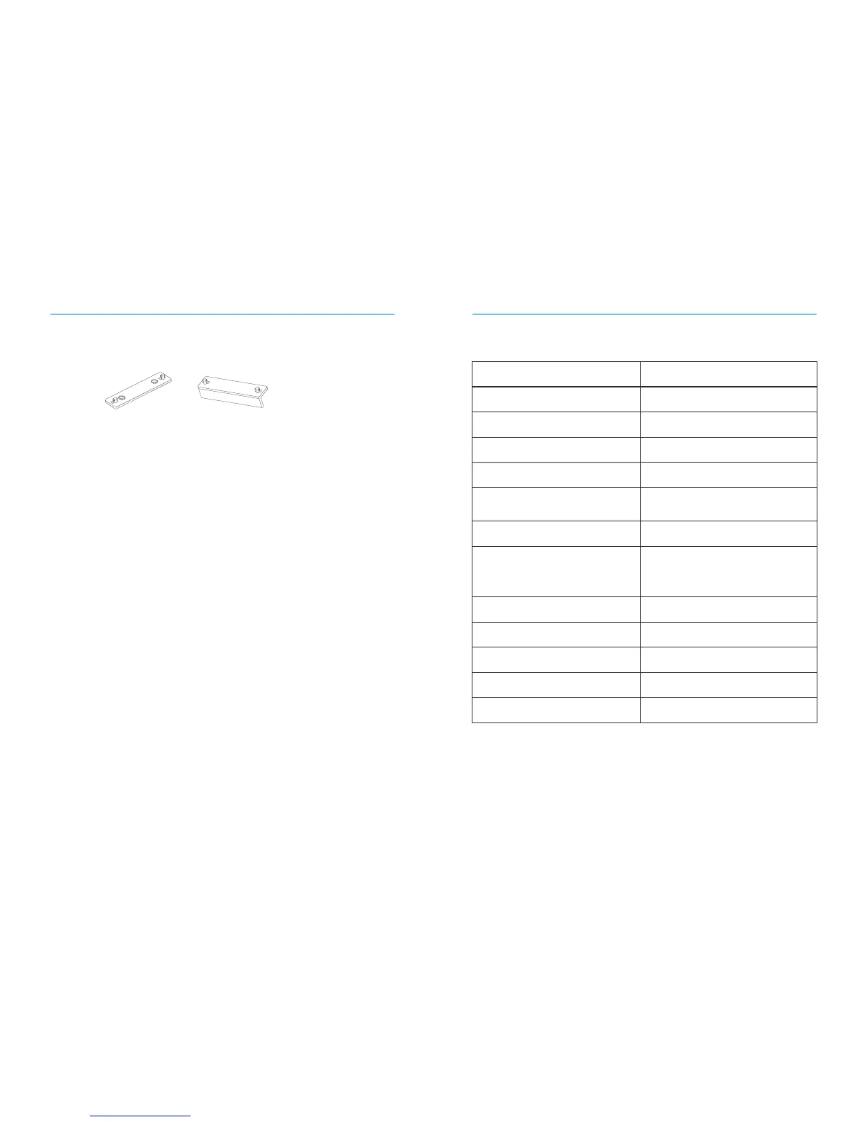
Control Panel Installation
Wall Mount
When mounting the Control Panel to the wall, first install the wall mount using the
screws supplied, then slide the Control Panel into the wall mount in an upward motion.
The wall mount secures the tamper switch in place.
Desk Stand
With the desk stand it is possible to place the Control Panel on a flat surface. The desk
stand can be mounted on the Control Panel by sliding it upwards.
Wall Mount Desk Stand
≤ 80m(open area/no interface)
Transmitting Distance
ABS plastic+Acr ylic
Housing Material
Technical Specifications