Packaging, Transport and Installation
17
Transport
– Mechanical or electronic components may be damaged.
• The machine may not be knocked, shaken or thrown during
transport.
3.10 Installation of the Device
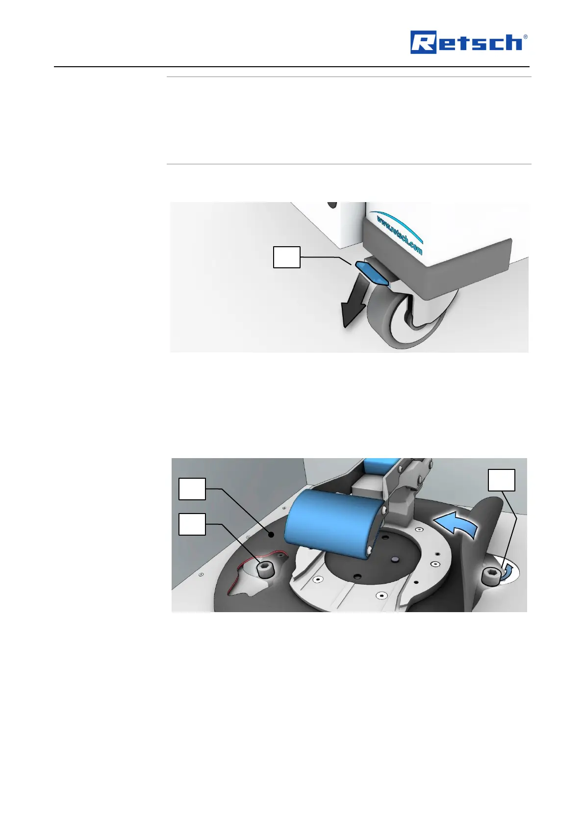
: Locking the transport rollers
• Place the device on a firm surface.
Please refer to the “Technical Data” chapter for further parameters.
The device must be locked before it is put into operation.
• Press the locking lever (FH) of the two front rollers down.
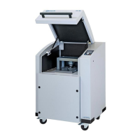
3.11 Removing the Transportation Lock
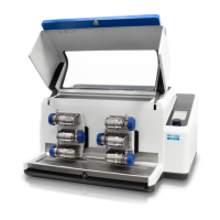
: Transport lock access
The drive unit of the device is locked during transport.
Before putting into operation for the first time, the two cylinder screws (ZS) fitted under the
rubber cover (GA) must be removed.
• Lift up the rubber cover (GA).