Rexroth EcoDrive 03 DKC**.3-040...200 Instructions for Use 5-7
DOK-ECODR3-DKC40*200UL-IB01-EN-P
Type No. of pins Design
connection block 2 / 3 / 3 screw-in connection for
ring terminals M5
Fig. 5-13: Design
min. tightening torque
[Nm]
max. tightening torque
[Nm]
2.5 3.0
Fig. 5-14: Tightening torque
Cross section
single wire
[mm²]
max. connectable
cross section
[mm²]
Wire Size
in AWG
gauge no.:
-- 25 --
Fig. 5-15: Connection cross section
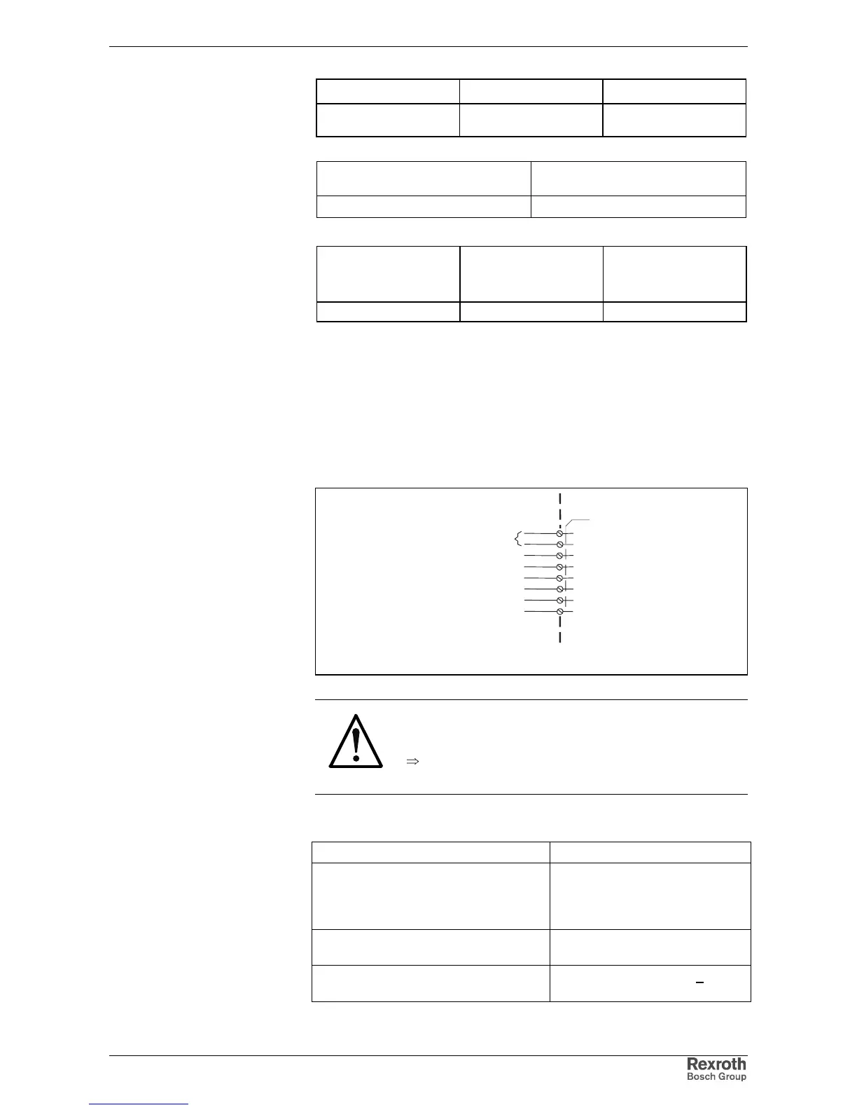
DC bus connection
The DC bus connection connects several controllers to each other plus it
connects controllers together with auxiliary components
• Increase allowed DC bus continuous power
• Increase allowed bleeder continuous load
• Allow connections for "Central supply"
device-external device-internal
AP5301F1.FH7
X5
L+
L-
DC bus connection
Fig. 5-16: DC bus connection
CAUTION
Damage possible if DC bus connections L+ and
L- are reversed!
⇒
Make sure polarity is correct.
If the DC bus rails supplied do not make a connection possible, then use
short twisted wires to do so.
wire length:
max. 2 x 1 m
wire cross section:
min. 10 mm²,
not smaller than the cross
section of the mains supply
lead
wire protection
With a fuse in the mains
connections
Voltage resistance of individual wires
to ground
> 750 V
(e.g., litz wires - H07)
Design:
Tightening torque:
Connection cross section:
Connection
DC bus:
wire
DC bus: