nRF52832
www.szrfstar.com V1.3 - Sep., 2020
Shenzhen RF-star Technology Co., Ltd. Page 15 of 58
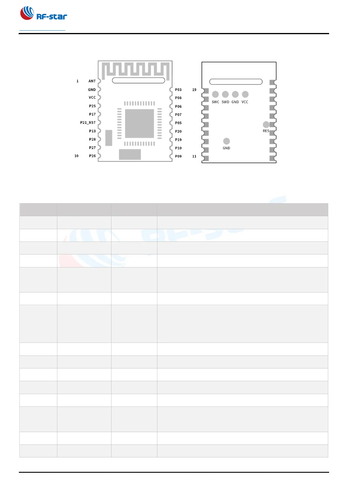
Figure 7. Pin Assignment of RF-BM-ND08(I)
Table 3. Pin Functions of RF-BM-ND08(I)
Power supply: 1.7 V ~ 3.6 V. Recommended to 3.3 V.
Broadcast state indicator: in high level during broadcast, in low
level during connection (always on)
When the module is in sleep state, the module can be awakened
through this IO.
Active on falling edge
All parameters will be reset to factory settings after this pin is
set low for 3 s.
(Require ToSend, send request) output signal, used to indicate