EasyManuals Logo

RF-Star nRF52832 User Manual

RF-Star nRF52832
59 pages
To Next Page IconTo Next Page
To Previous Page IconTo Previous Page
Page #53 background imageLoading...
Page #53 background image
nRF52832
www.szrfstar.com V1.3 - Sep., 2020
Shenzhen RF-star Technology Co., Ltd. Page 52 of 58
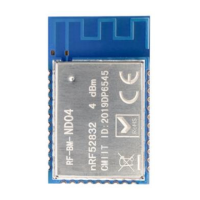
The default delivery is IPEX connector mode. Under IPEX connector mode, C1 is off and C2 is welded. If you would like
to change to half-hole antenna output mode, please disconnect C2 and weld C2. The locations of C1 and C2 (8 pF) are
shown in the figure below.
Figure 10. Antenna Output Mode Change
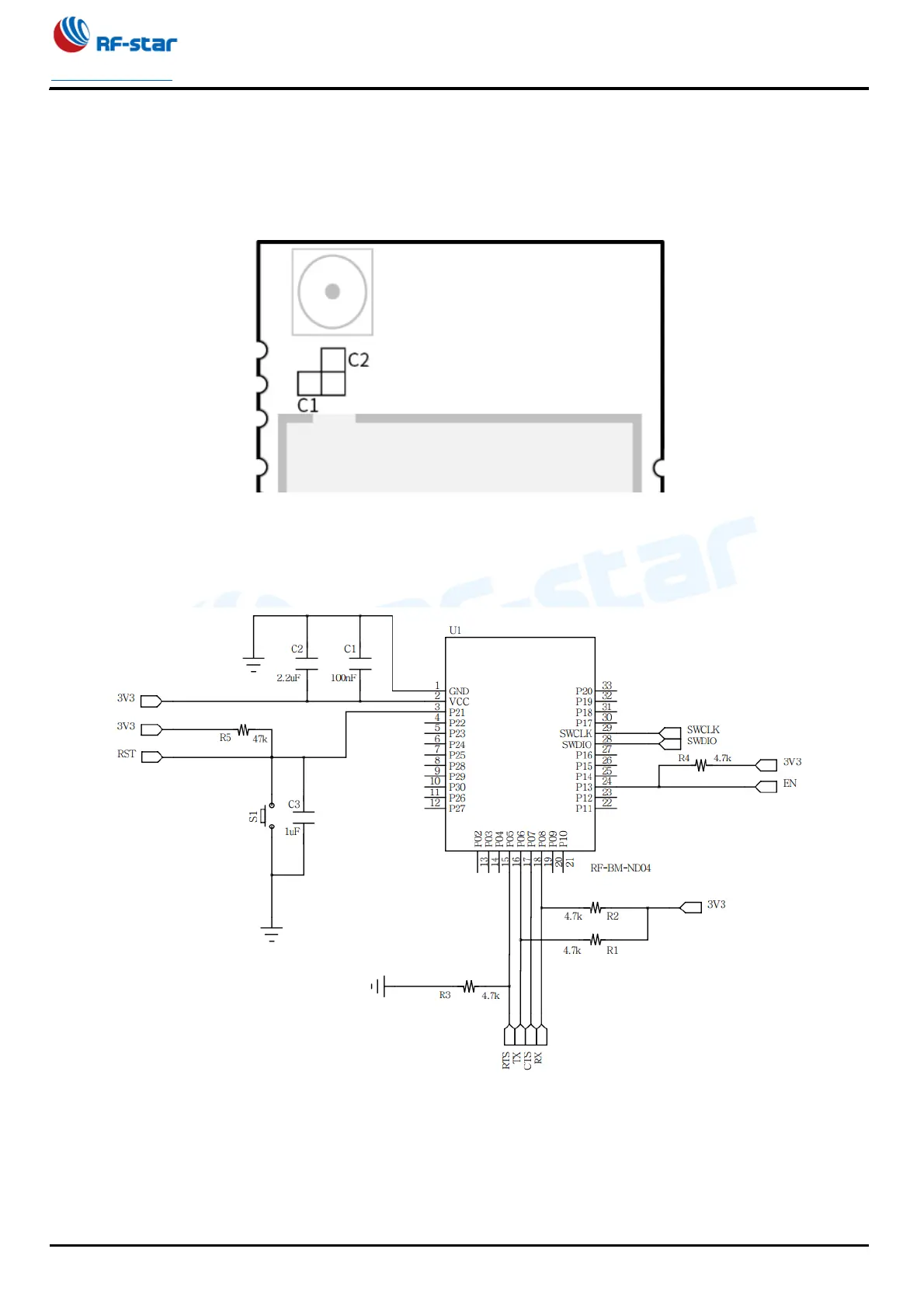
10.2 Reference Design
Figure 11. Reference Design of RF-BM-ND04

Table of Contents

Questions and Answers:

Question and Answer IconNeed help?

Do you have a question about the RF-Star nRF52832 and is the answer not in the manual?

RF-Star nRF52832 Specifications

General IconGeneral
BrandRF-Star
ModelnRF52832
CategoryControl Unit
LanguageEnglish