5010e_513.doc / 22.01.10
2 INSTALLATION
2.1 DELIVERY
Check the device and contents of the enclosed box as follows on visible transport damages and completeness:
1 Operator’s Manual
1 Aspiration tube
1 Axis printer paper
1 Dust cover
2 Fuses for line power
1 Mains cable
2 Printer paper
1 Pump tube with joints
1 Ribbon band printer
1 Standard cuvette adaptor
1 Top cover small for printer
1 Waste tube
Inform the sales office immediately about transport damages. Keep the original packaging for a possible
return.
2.2 PREPARATION FOR INSTALLATION
Place the device on a stable, level surface. Do not obstruct the input air at the bottom and the waste air at the
back plate to guarantee the ventilation of the device.
If the device was exposed to extraordinary fluctuation in temperature and/or humidity, it must acclimatize suffi-
ciently before operation.
Before connecting the waste tube to the pump tube remove pump tube at both ends from the metal
clamps. The waste tube of the flow-through system must be led through the tunnel to the backside of the device
(chapter 3.2 - BACK) and then into any drain tank.
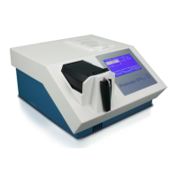
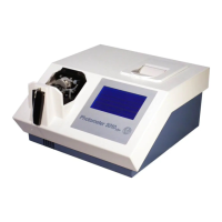
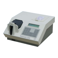
2.3 INSTALLATION
Photometer 5010 operates at any line voltage between 90 V
AC
and 264 V
AC
at 50/60 Hz. The device plug of the
mains cable must be put into the socket at the back of the device and the mains plug into a grounded mains
socket.
While connecting or disconnecting an external device (PC, printer) to Photometer 5010 both devices
must be switched off.
Switch on Photometer 5010 by the mains switch at the back.
Greeting screen:
After switching on copyright, website, type of
device and version designation are displayed
and - in the case of activated printer - printed
out.
(c) ROBERT RIELE
GmbH & Co KG
PHOTOMETER 5010
V5.13a 02/09/09 D
www.riele.de
ROBERT RIELE GmbH & Co KG Page 8 2 - INSTALLATION