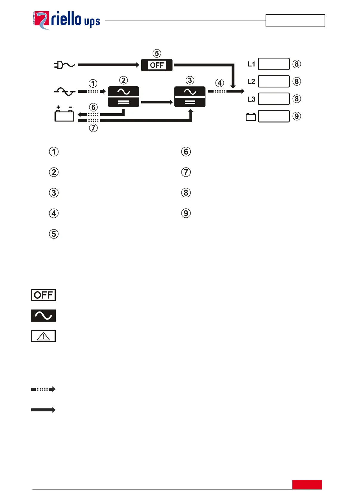
The first page is a schematic view of UPS operating status:
The diagram shows the status of the three power logical modules (PFC Converter, Inverter, Automatic Static
Bypass).
Each module can take on one of the following status types:
Module on in normal operating mode
The following symbols show the power flow to and from the batteries (uncharged/charged) and the status of
input and Inverter contacts:
Module on in normal operating mode