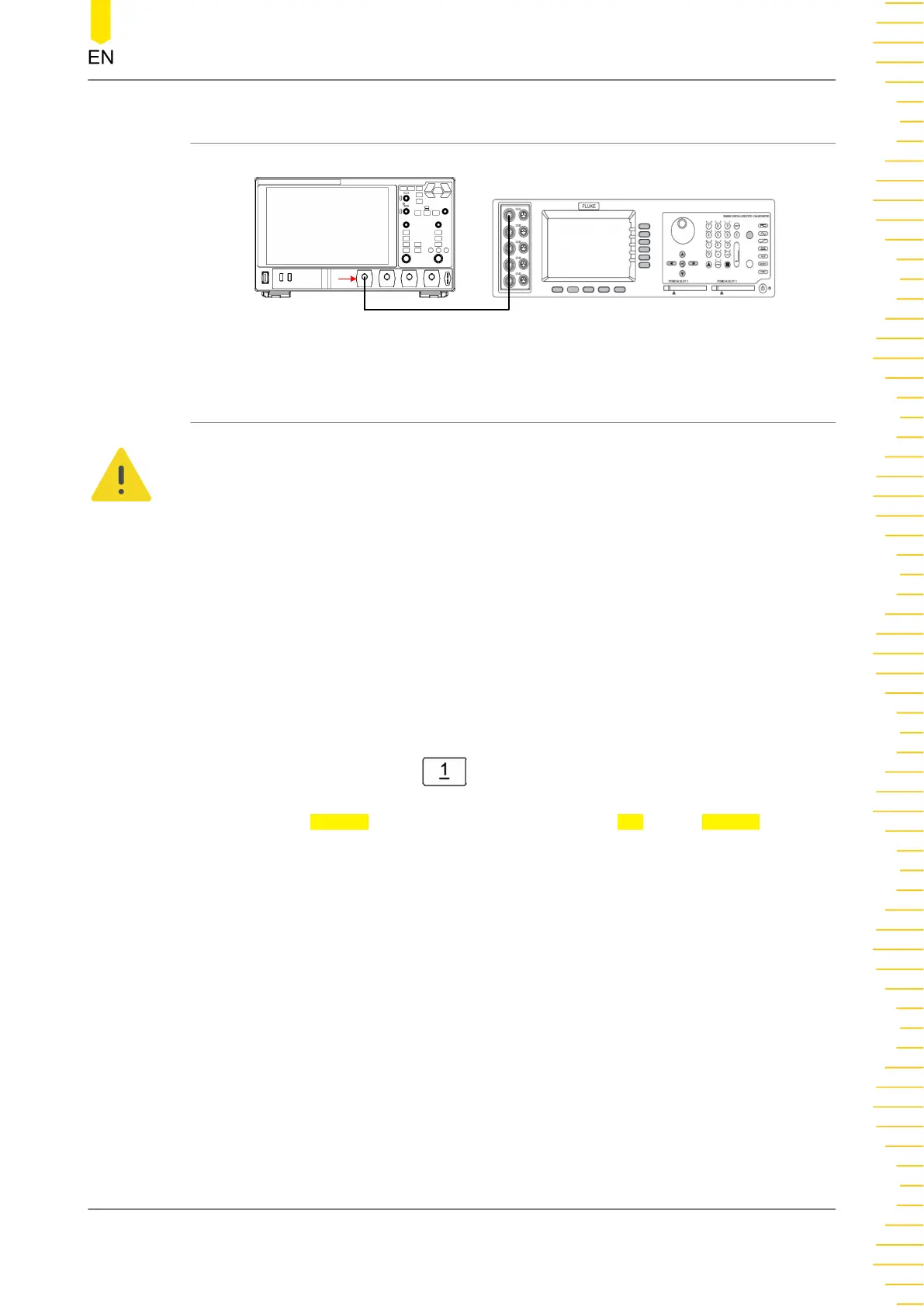
5.3.2 Test Connection Diagram
Fluke 9500B
CH1
DHO1000
Figure 5.2 Input Capacitance Test Connection Diagram
5.3.3 Test Procedures
WARNING
Before connecting, disconnecting, or moving the test hookup, disable the output of the
signal generator to avoid causing the dangerous voltage.
1. Connect the active head of Fluke 9500B to CH1 of the oscilloscope, as shown in
Figure 5.2
.
2. Configure the oscilloscope:
a. To enable CH1, perform any of the following operations:
- Click or tap the channel status label at the bottom of the screen to enable
CH1.
- Press the front-panel
key to enable the channel.
- In the Vertical menu, select the CH1 tab. Select ON for the Display item to
turn CH1 on.
b. Set the vertical scale of CH1 to 50 mV/div.
3. Turn on Fluke 9500B; set its impedance to 1 MΩ and select the capacitance
measurement function. Read and record the capacitance measured.
4. Adjust the vertical scale of CH1 to 500 mV/div; read and record the capacitance
measured.
5. Turn off CH1. Measure the capacitances of CH2, CH3, and CH4 respectively using
the method above and record the measurement results.
Performance Verification Test
Copyright ©RIGOL TECHNOLOGIES CO., LTD. All rights reserved.
DHO1000 Performance Verification
15
 Loading...