5.3.4 Test Record From
Channel Vertical Scale Test Result Limit Pass/Fail
CH1
50 mV/div 19 pF ± 3 pF
500 mV/div 19 pF ± 3 pF
CH2
50 mV/div 19 pF ± 3 pF
500 mV/div 19 pF ± 3 pF
CH3
50 mV/div 19 pF ± 3 pF
500 mV/div 19 pF ± 3 pF
CH4
50 mV/div 19 pF ± 3 pF
500 mV/div 19 pF ± 3 pF
5.4 DC Gain Accuracy Test
5.4.1 Specification
DC Gain Accuracy
Specification ±2% x Full Scale
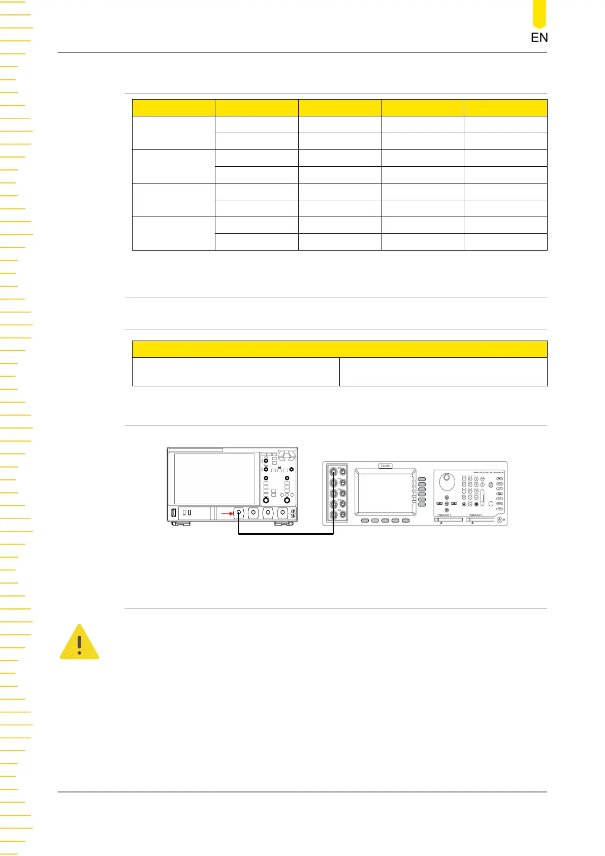
5.4.2 Test Connection Diagram
Fluke 9500B
CH1
DHO1000
Figure 5.3 DC Gain Accuracy Test Connection Diagram
5.4.3 Test Procedures
WARNING
Before connecting, disconnecting, or moving the test hookup, disable the output of the
signal generator to avoid causing the dangerous voltage.
1. Connect the active head of Fluke 9500B to CH1 of the oscilloscope, as shown in
Figure 5.3
.
2. Set the impedance of Fluke 9500B to 1 MΩ.
3. Output a DC signal with +3 mVdc voltage (Vout1) via Fluke 9500B.
Performance Verification Test
DHO1000 Performance Verification
16
Copyright ©RIGOL TECHNOLOGIES CO., LTD. All rights reserved.
 Loading...