RIGOL Chapter 8 Protocol Decoding
8-18 MSO2000A/DS2000A User’s Guide
CAN_H: the actual CAN_H bus signal.
CAN_L: the actual CAN_L bus signal.
Differential: the CAN differential bus signals connected to an analog
channel using a differential probe. The positive lead of the probe connects
the CAN_H bus signal and the negative lead connects the CAN_L bus signal.
3. Baud
Press Baud to select a baud rate (100 kb/s, 125 kb/s, 250 kb/s, 400 kb/s, 500
kb/s (default), 800 kb/s, 1 Mb/s or User) that matches the CAN bus signal. When
“User” is selected, press Setup and use or the inner knob of the navigation
knob to adjust the baud rate at a relatively smaller step or turn the outer knob of
the navigation knob to adjust the baud rate at a relatively larger step. The range
is from 10 kb/s to 1 Mb/s.
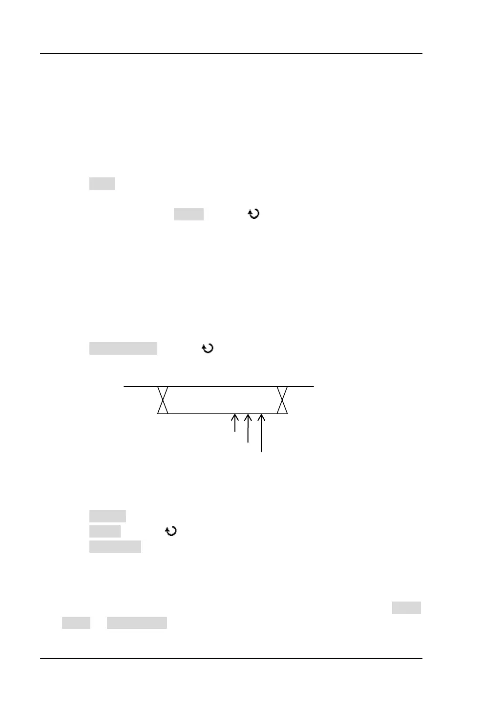
4. Sample Point
The Sample point is a point within a bit’s time. The oscilloscope samples the bit
level at this point. The sample position is represented by the percentage of “the
time from the start of the bit’s time to the sample point time” in the “bit’s time”.
Press Sample Point and use to adjust this parameter with a step of 1%.
The range is from 5% to 95% and the default is 50%.
Figure 8-12 Sample Position Schematic Diagram
5. Display-related Setting
Press Format to set the bus display format to Hex, Decimal, Binary or ASCII.
Press Offset and use to adjust the vertical display position of the bus.
Press BusStatus to enable or disable bus display.
6. Event Table
The event table displays the decoded data, the corresponding line number, time,
frame ID, DLC, CRC and ACK information in table or details format. Press Event
Table Event Table to select “ON” (This operation is only available when
1bit
60%
70%
www.GlobalTestSupply.com
Find Quality Products Online at: sales@GlobalTestSupply.com