8 ProSYS Quick Programming Setup
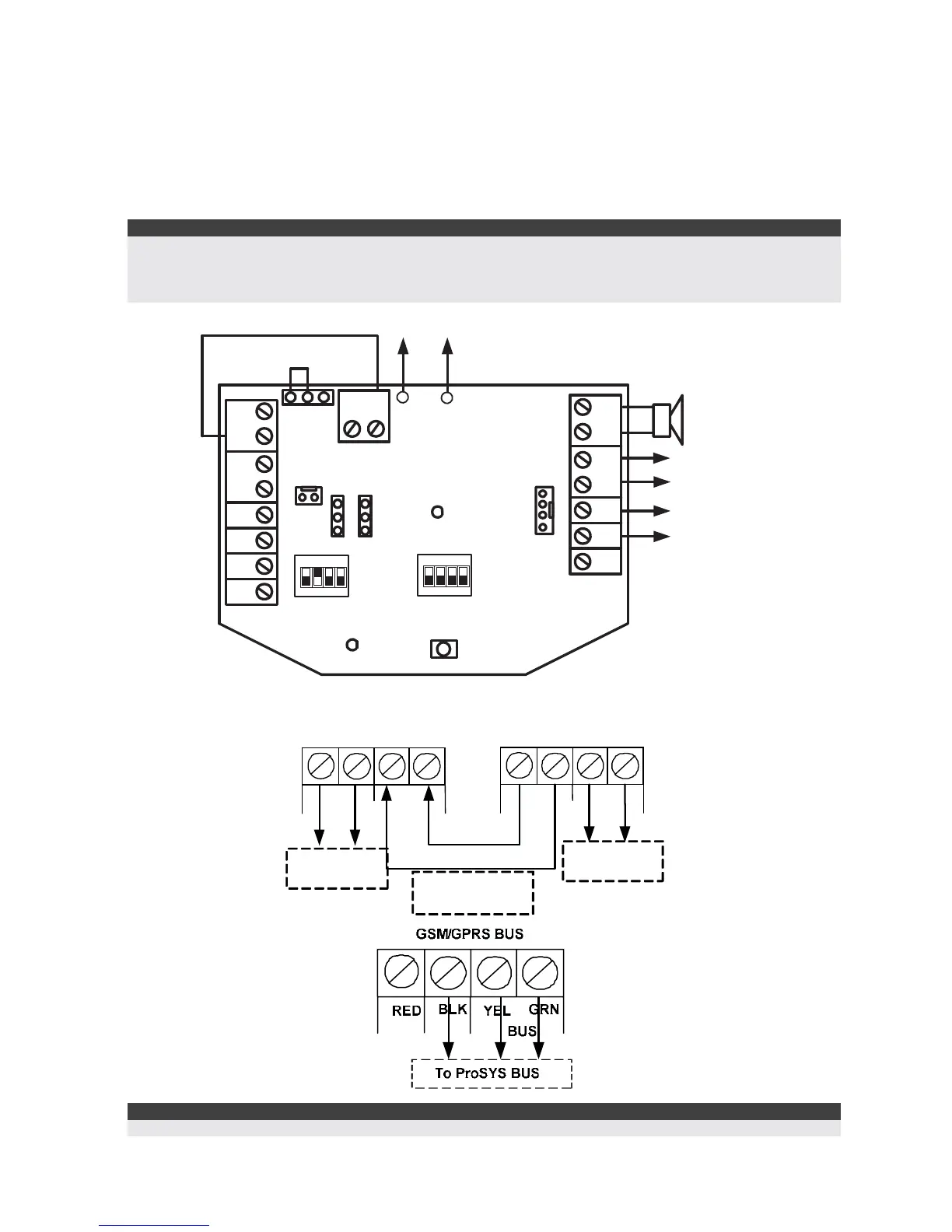
7.2 ProSound - BUS Siren Connection
Connect the siren according to the diagram. Set the related Dipswitches for BUS mode
operation.
Dipswitch CONFIG 2 should be in ON position for ProSound BUS connection
Dipswitch CONFIG 4: Defines the siren sound rhythm (ON = Slow, Off = Fast)
Dipswitch ID1: 1-3: Set ID BUS Number. Up to 8 sirens can be connected to the ProSYS
Dipswitch ID1 4: Set different siren sound
Notes:
The PROX and TRBL outputs are deactivated in BUS mode configuration.
To protect the battery against deep discharge, the battery will automatically disconnect below 10.5 VDC.
The siren will not operate when a battery is not connected.
The ProSound is not UL listed.
BUS
GRN
YEL
COM
BLK
SPE AKER
AUX
RED
LED
TRBL
PROX
TAMPER
F
R
C + C - ST
12 3 4
ON
ID1
TAMPER
PS
+
-
BLK
RED
MAN
AUTO
C +
C -
TRIG STROB
LED2
POWER
To Internal
Speaker
To
ProSYS
Panel
BUS
12 34
ON
CONFIG
INT EXT
To
Battery
(To Int.
Tam per)
7.3 Wiring the GSM
Important:
Do NOT make any connection to the RED Power terminal from the security panel.
PHONE
LINESE