ProSYS Quick Programming Setup 9
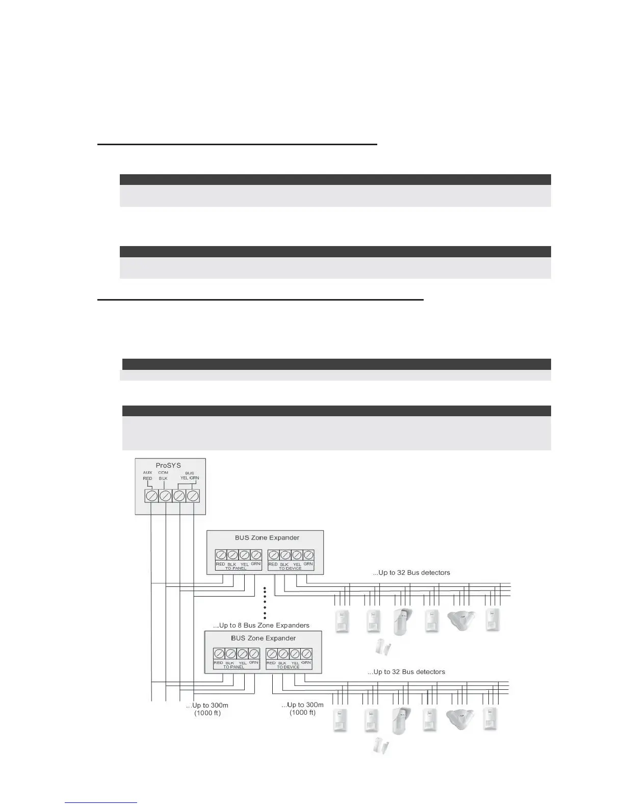
7.4 Wiring BUS Detectors
The ProSYS supports integration of BUS detectors. Up to 32 addressable BUS detectors can be
assigned to the main unit without the need to add any additional hardware zone expanders
(using virtual zones).
To assign more than 32 BUS detectors (up to 128) you need to add BUS Zone Expanders.
For full installation instructions refer to the instructions supplied with each BUS detector.
Connecting BUS Detectors to the ProSYS panel:
1. Set the BUS detector ID number (1-32) using the detector's Dipswitches.
Note:
For WatchOUT, LuNAR, and WatchIN set the switch that defines the detector operation mode to BUS
mode.
2. Wire the BUS terminals (RED), COM (BLK), BUS (YEL) and BUS (GRN) to the ProSYS
BUS.
Note:
For maximum operation stability, it is best NOT to exceed a total 300 meters (1000 feet) of wiring from
the BUS detector to the ProSYS panel.
Connecting BUS Detectors using a BUS Zone Expander:
1. Set the BUS Zone Expander ID number (1-8) using the Dipswitches SW1 1-3.
2. Using SW2 Dipswitches, set the number of zones this expander will support (8,16,24,32)
3. Wire the BUS Zone Expander terminals marked as TO PANEL to the ProSYS BUS.
4. Set the BUS detector ID number (1-32) using the detector's Dipswitches.
Note:
Do not repeat the same ID twice on the same BUS zone expander.
5. Wire each detector's BUS terminals to the relevant BUS zone expander's terminals
marked as TO DEVICE.(see figure below)
Note:
For maximum operation stability, it is best NOT to exceed a total of:
• 300 meters (1000 feet) of wiring from the BUS Zone Expander to the ProSYS panel.
• 300 meters (1000 feet) of wiring from the BUS Zone Expander to the last BUS detector.