6 WatchOUT DT Installation Manual
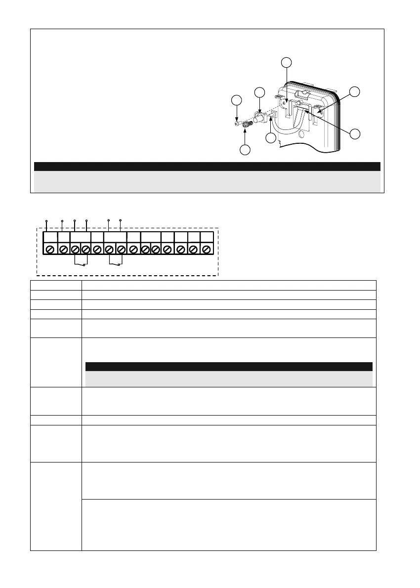
Changing Back Tamper position
The back tamper is by default secured on the right
side of the internal base (rear view). If you wish to
move it to the left side (rear view), do the following
(Figure 5):
1. Remove tamper screw 1 in order to release the
tamper from position 7.
2. Ensure tamper spring 2 rests over tamper wire
base 4.
3. Ensure plastic tamper bracket 3 rests over both
2 and 4.
4. Secure tamper screw 1 into 3 over position 6.
Figure 5
Left Side
Tamper
Right Side
Tamper
3
6
1
2
4
7
5
Notes:
1. Verify that you hear a "Click" when attaching the tamper spring to the wall.
2. For pole installation, the tamper can be moved to the bottom right-hand side of the internal base.
Terminal Wiring
+-
SET/
UNSET
LEDs
ENABL
AM
YEL
FREE
ALARM
TAMPER
GREEN
FREE
DUST TEST
12VDC
N.C
N.C
WatchOUT DT - PCB
+,-
12 VDC
ALARM
N.C relay, 24VDC , 0.1A
FREE YEL
This terminal is a free pin that can be used to connect wires and EOL resistors
TAMPER
N.C relay, 24VDC , 0.1A
FREE
GREEN
This terminal is a free pin that can be used to connect wires and EOL resistors
AM
Normally closed AM relay output (
24VDC, 0.1A) indicates Anti Masking alarm or
any trouble in the detector (Not including dust/dirty lens).
Note:
When a vibration detector is installed and DIP8 is defined as Enabled this relay also opens
momentarily when vibration event occurs.
LED
ENABLE
Used to remotely control the LEDs when DIP1 is set to ON.
Enable: input is +12V OR no terminal connection
Disable: Connect the input to 0V
DUST
N.O. collector max 70 mA. Indicates that the lens is dirty and requires cleaning.
TEST
Used to perform remote alarm testing to the detector by applying 0 volts to this
terminal.
Success: Alarm relay is momentary opened.
Failure: AM relay is opened
This input enables to control Anti-masking and LEDs operation in accordance to
the system status, Set (Arm) / Unset (Disarm).
While the system is armed this feature prevents an intruder from gaining
knowledge of the detector’s status and disables Anti-masking detection.
SET/
UNSET
System Status Input Status AM Relay LEDs
Set (Arm) 0V Off Off
Unset (Disarm) 12V or no connection On* On**
* DIP7 is ON (Anti masking enabled)
** DIP1 is ON (LEDs enabled) and LEDs ENABLE input terminal is enabled
(+12V OR no terminal connection)