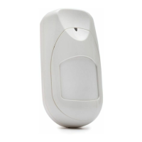
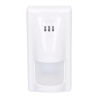
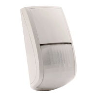
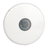
WatchOUT DT Installation Manual 7
English
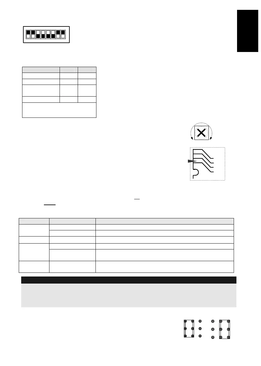
DIP Switch Settings
12345678
ON
Factory
Default
DIP 1: LEDs operation
On: LEDs Enabled
Off: LEDs Disabled
DIP 2-3: Detection Sensitivity
Sensitivity DIP2 DIP3
Low Off Off
Mid Off On
Normal
(Default)
On Off
Maximum* On On
* In maximum sensitivity sway
recognition is disabled to achieve
maximum sensitivity
DIP 4: Alarm condition
On: PIR or MW
Off: PIR + MW
DIP 5: Detector's optics
On: Barrier / Long range
Off: Wide angle
DIP 6: Red LED /3 LED
On: Red LED only
Off: 3 LEDs
DIP 7: Anti masking operation
On: Enabled
Off: Disabled
DIP 8: Vibration detection (applicable to versions
with Vibration sensor installed)
On: Enabled
Off: Disabled
Microwave Adjustment
Adjust Microwave coverage area by using the trimmer on the PCB.
MIN
MAX
Walk test
Two minutes after applying power, walk test the protected area to
verify proper operation.
For installations on uneven surfaces slide the PCB inside the internal
base to the appropriate setting according to the desired height (1.0m,
1.5m, 2.2m, 2.7m) as printed on the bottom left corner of the PCB or
use the standard swivel accessory.
For reducing the detection range, slide the PCB up
or tilt the
swivel down
.
1.00M
1.50M
2.20M
2.70M
PCB
LEDs Display
LED State Description
Steady Indicates PIR detection
YELLOW
Flashing Indicates AM (Anti mask) detection
GREEN
Steady Indicates MW detection
Steady Indicates ALARM
RED
Flashing Indicates malfunctioned communication with ProSYS (BUS
mode only)
All LEDs
Flashing (One
after another)
Unit initialization on power up
Notes:
1. DIP-Switch 1 should be in ON position to enable LED indications.
2. Only one LED is active at any one time. For example, in the case of both PIR and MW detection, either the
steady YELLOW LED or the steady GREEN LED is displayed (the first to detect), followed by the Alarm RED
LED.
Relay Mode / BUS Mode Jumper
J-BUS jumper (located on the PCB between the red and green LEDs)
is used to define the detector’s mode of operation as follows:
Relay
Mode
BUS
Mode