WatchOUT DT Installation Manual 9
English
Note:
The Tamper spring S5 (Figure 7) should make contact with the wall through the tamper spring holes M2 or
M3 on the CSMA. Make sure to hear the tamper "Click" when connecting to the wall.
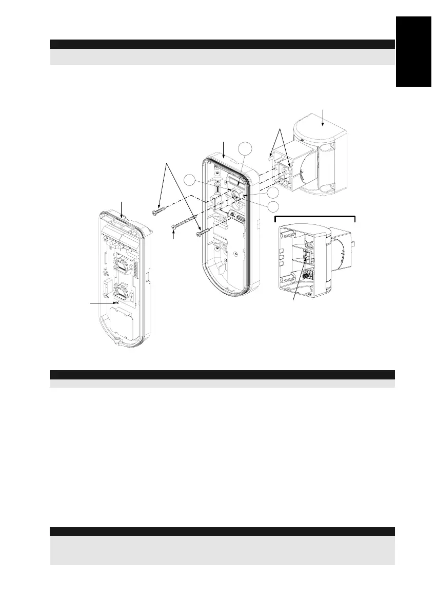
7. Insert tamper wires and external cable wiring from Standard Swivel through knockout W1 on
the external base (Figure 6, Detail B).
8. Connect the external base to the swivel using the dedicated snaps (Figure 7).
PCB
External Base
Internal Base
Angle Locking
Screw
(See Note 2)
See Detail A
Swivel to External Base
Connecting Screws
Detail A
Swivel Assy
Connecting Screw
(See Note)
Snaps
S1
W1
S2
S3
Figure 7
NOTE:
Do not open or close the Swivel Assy Screw since it is used for connecting the swivel parts only.
9. Secure external base to swivel with two screws fastened to knockouts S1 and S2 (Figure 7).
10. Insert the supplied angle locking screw from the external base through the angle locking screw
knockout S3 on the external base to the standard swivel (Figure 7).
11. Tilt and Rotate the Standard Swivel to the desired position. Once the Standard Swivel is in the
desired position, secure the angle locking screw.
12. Line up the internal base onto the external base. Insert all wiring cables through the internal
base.
13. Secure internal base to external base (Lock I1, Figure 2).
14. To readjust the Standard Swivel when the PCB is installed (Figure 7):
a. Bend down the black foam located below the RED LED on the PCB (enough to reach the
Swivel locking screw).
b. Use a Philips screwdriver to release the locking screw (see Figure 8).
c. Tilt and/or Rotate the Standard Swivel to the desired position.
d. Secure the angle locking screw.
Note:
When marks on the two movable parts are aligned (Figure 8), the Standard Swivel is in 0°
vertical /horizontal position. Each click from this position represents shifting of 5° in vertical / horizontal
position.
15. Close the front cover (Lock C1, Figure 1) and walk test the detector.