3 - SAFETY DEVICES AND EQUIPMENT 28
3.1 YACHT’S AREAS
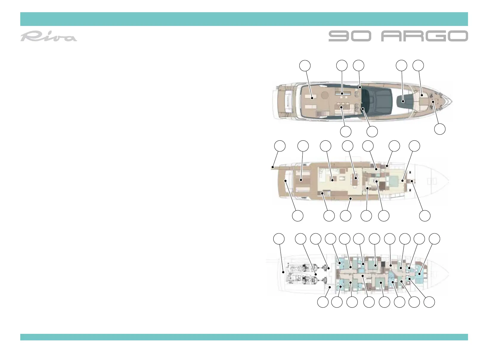
The diagram below, represents the yacht’s general layouts, divided accord-
ing to the areas they include:
1. Fly bridge sun-deck area
2. Bar unit
3. Side walk-around access door
4. Bow sun-deck area
5. Bow sofa
6. Anchorage and mooring area
7. Fly bridge helm station
8. Fly bridge dining room
9. Gangway
10. Stern cockpit
11. Salon area
12. Dining room area
13. Galley area
14. Crew area access ladder
15. Owner’s cabin
16. Owner’s bathroom access ladder
17. Pilot house
18. Guest area access ladder
19. Walk-around
20. Fly bridge access ladder
21. Garage hatch
22. Garage
23. Engine room area
24. Technical room
25. Port guest cabin bathroom
26. Port guest cabin
27. Port VIP cabin bathroom
28. Port VIP cabin
29. Crew galley
1
22 23 24 2625
9 10 11 12 13 14 15
27 28 29 30 31 32
363740 39 38 35 34 33
161718192021
2 3 4
78
6
5