5: Technical Information
Pin
Number
Function Direction
1 DCD + carrier detect to computer
2 RX - received data to computer
3 TX - transmitted data from computer
4 DTR + data terminal
ready
from computer
5 GND signal ground not applicable
6 DSR + data set
ready
to computer
7 RTS + request to
send
from computer
8 CTS + clear to send to computer
9 RI + ring indicator to computer
+ indicates active high
- indicates active low
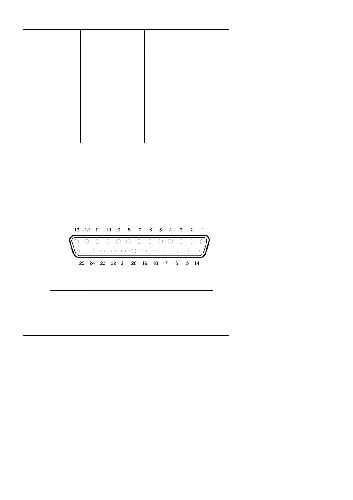
Parallel Connector
There is one parallel connector at the back of your RM One
computer:- AT compatible 25-way female D-type connector. Note:
EPP/ECP signals are not shown.
Pin
Number
Function Direction
1 - strobe from computer
2 + data bit 0 (lsb) from computer
3 + data bit 1 from computer
59