CAN Networking on Roboteq Controllers
46 CANBus Networking Manual V2.0 July 8, 2019
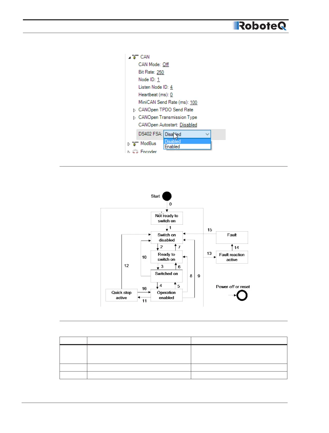
FIGURE 4-1. FSA Configuration
Figure 4-2 describes The states and the transitions of the finite state machine, while Table
4-3 describes the actions and the events of the transitions.
FIGURE 4-2. Power Drive System Finite State Automation
TABLE 4-3. Transition Events and Actions
Transition Event(s) Action(s)
0
Automatic Transition after power on or reset
application (if ^FSA 1), or when ^FSA is set
from 0 to 1.
None
1 Automatic transition None
2 Shutdown Command None
 Loading...