35
37 pin connector. Check the wiring here to see if there is a broken wire. On robots with
characters driving, these wires go to the Character Control Board in the chest area. Check
these connections and look at the Character Control Board in the end of this manual for
correct placement on the circuit board.
Check the fuse on the fuse block.
The eyes work but not properly:
Check switches 3 and 4 in the battery compartment of the RC transmitter. They should be
in the normal (blue) position.
Put the joystick sliders in the middle.
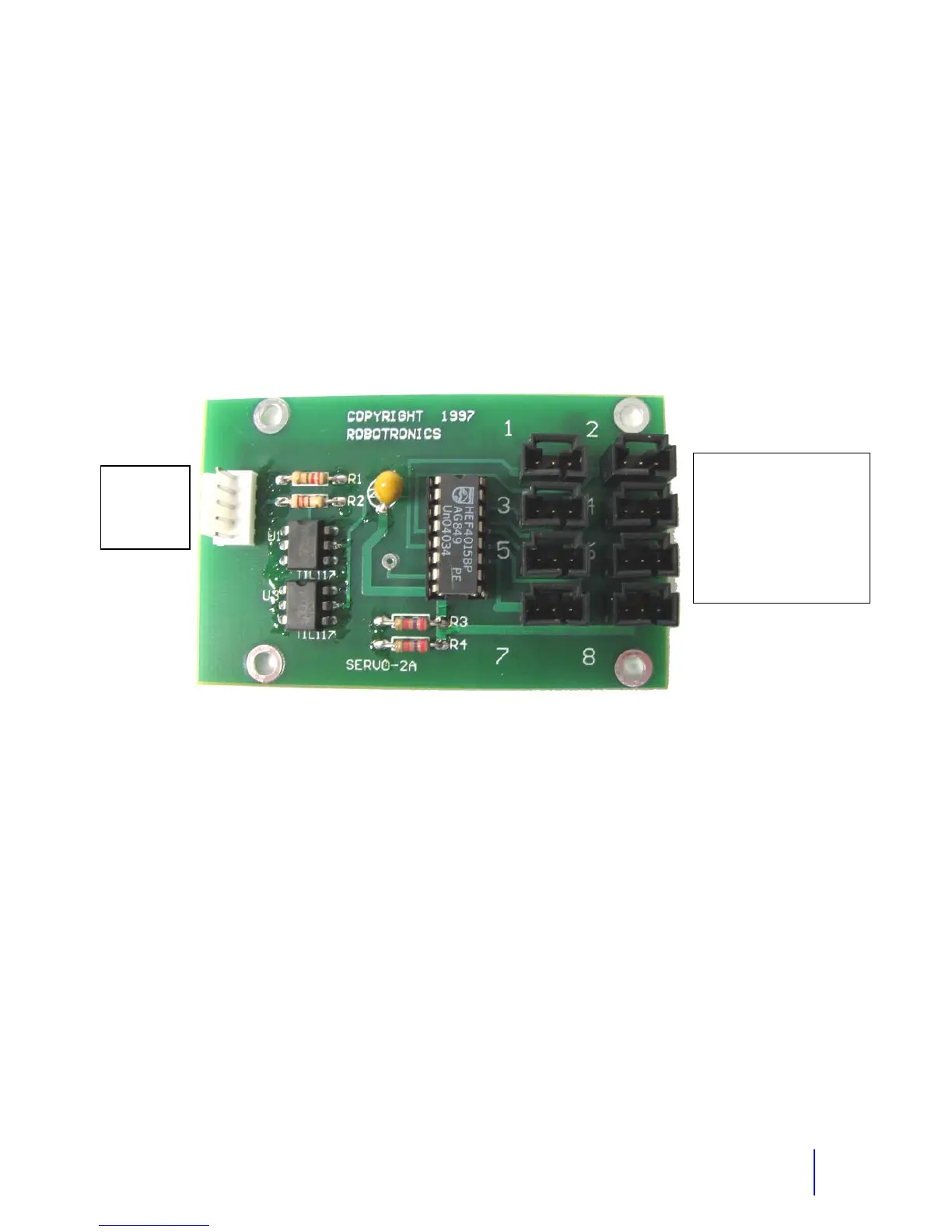
1 Left Eyelid
2 Left Eyelid Reverse
3 Right Eyelid
4 Right Eyelid Reverse
5 Eyes L/R
6 Eyes L/R Reverse
7 Mouth Servo
8
Red + 5 V
Black Gnd
Gray
Yellow
Black
E
e and Mouth Servo Board