39
Stop Arm and Crossing Arm for School Bus Robots – Barney and
Buster
Stop Arm
To activate the stop arm function, the operator will hit the switch on the RC that is labeled stop
arm/reds. The signal from the RC is sent to the receiver in the robot. This signal goes to the
main processor and two signals are in turn sent from the processor. One is sent to the red light
output transistors to flash the red lights. The other is a servo signal that is sent out to the servo-
motor via the 3-pin servo output from the main board. See the main board diagram to locate
these outputs. The servo signal goes to a circuit board that provides the 5 Volt power for the
servo and isolates the signal from noise. This board is the 5- Volt Isolation circuit board and is
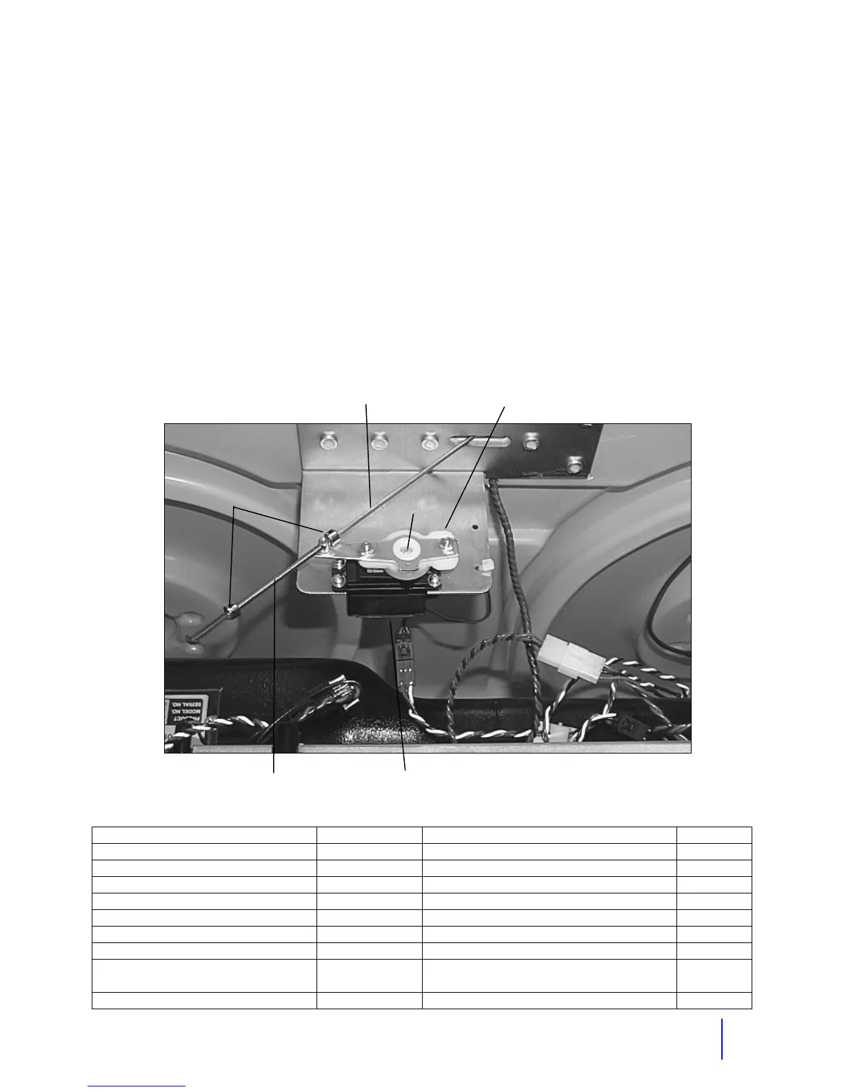
located off the back left corner of the main board. Parts of the stop arm include the stop sign,
servo, ball link, rod, spring, servo arm and set screw. To adjust the pull in tension and position
of the arm, loosen the set- screw on the rod and increase or decrease the tension on the spring.
Description Part # Description Part #
Stop Arm
Servo Motor Futaba 3003/FS100 722004 Tension Springs 712001
Servo Arm Assembly 500014 Stop Arm Sticker 715017
4-40 Threaded Rod End 791144 Stop Sign 990089
4-40 Ball Link 791259 Stop Arm Metal Bracket 930401
3-32 Collar 791138 Stop Sign Bulb 800024
¾ inch Stop Sign Red Lens 800025
Crossing
Arm
Futaba S3302 Servo 722002 Servo Arm for Crossing Gate M
Stop Arm Rod
4-40 Threaded Rod End
Servo Arm
Stop Arm Servo Motor
Set Screw
Tension Spring
3/32” Collars