34
4.2.3 Alarm/Blower stopping connection
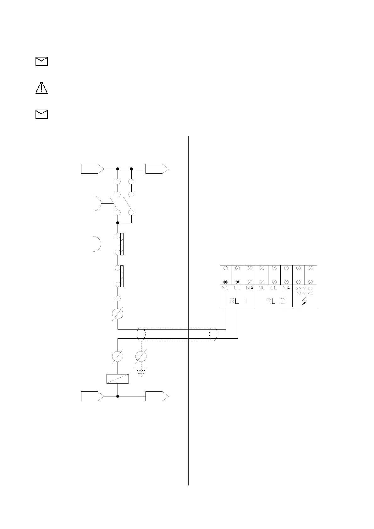
Connect the RL1 switch in series with the starting switch KV of the electric motor starting panel.
NOTE : Use the NC connection because it is intrinsically safe in case of interruption of
SENTINEL electric supply.
WARNING
: The protection of the blower is granted only if the SENTINEL Alarm/Stopping
switch RL1 is connected to the starting panel like indicated in Fig. 6.
NOTE : Shield the SENTINEL Alarm/Stopping connection cables and do not lie out the cables
near the power cables
STARTING PANEL SENTINEL
Ancillary system Junction box
1
1
PM KV
PA
PT
2
2
1 Ancillary line RL1 Alarm/Stopping connector
2 Ancillary line NC Normally closet contact
PM Start key CC Commune Contac
PA Stop key NA Normally Open contact
PT Motor protection
KV Starting switch
Fig. 7