52 Rockwell Automation Publication 1766-UM001O-EN-P - September 2021
Chapter 3 Wire Your Controller
• Under normal conditions, the drain wire (shield) should be connected to
the metal mounting panel (earth ground). Keep the shield connection to
earth ground as short as possible.
• To ensure optimum accuracy for voltage type inputs, limit overall cable
impedance by keeping all analog cables as short as possible. Locate the I/
O system as close to your voltage type sensors or actuators as possible.
• The module does not provide loop power for analog inputs. Use a power
supply that matches the input transmitter specifications.
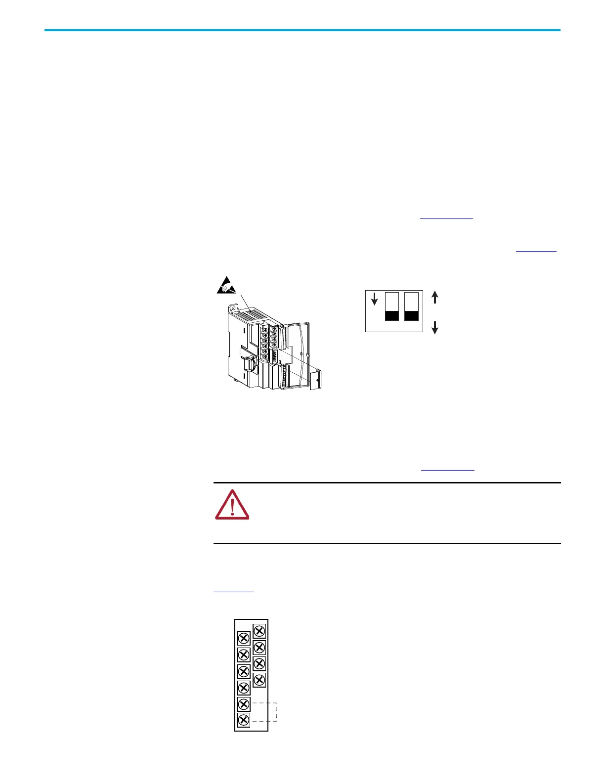
1762-IF2OF2 Input Type Selection
Select the input type, current or voltage, using the switches located on the
module’s circuit board and the input type/range selection bits in the
Configuration Data File. See MicroLogix 1400 Programmable Controllers
Instruction Set Reference Manual, publication 1766-RM001
. You can access the
switches through the ventilation slots on the top of the module. Switch 1
controls channel 0; switch 2 controls channel 1. The factory default setting for
both switch 1 and switch 2 is Current. Switch positions are shown in Figure 35
.
Figure 35 - 1762-IF2OF2 Switch Positions
1762-IF2OF2 Output Type Selection
The output type selection, current or voltage, is made by wiring to the
appropriate terminals, Iout or Vout, and by the type/range selection bits in the
Configuration Data File. See MicroLogix 1400 Programmable Controllers
Instruction Set Reference Manual, publication 1766-RM001
.
1762-IF2OF2 Wiring
Figure 36 shows the 1762-IF2OF2 analog expansion I/O terminal block.
Figure 36 - 1762-IF2OF2 Terminal Block Layout
ATTENTION: Analog outputs may fluctuate for less than a second when power is
applied or removed. This characteristic is common to most analog outputs. While
the majority of loads will not recognize this short signal, it is recommended that
preventive measures be taken to ensure that connected equipment is not
affected.
Current (ON) default
Voltage (OFF)
Switch location
V Out 1
V Out 0
IN 1 (+)
IN 0 (+)
I Out 1
I Out 0
IN 1 (-)
IN 0 (-)
COM
COM
Common connected internally.
 Loading...


