Publication IASIMP-QS003B-EN-P - October 2009 79
Prepare the Kinetix 6000 Multi-axis Servo Drive System Chapter 6
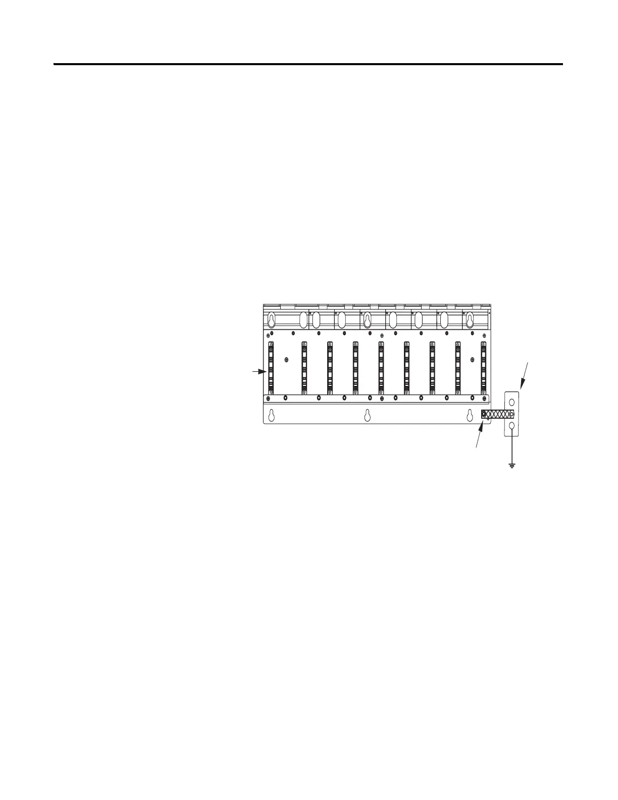
Mount and Bond the Power Rail
2094-PRS1 through 2094-PRS8
The Kinetix power rails support one integrated axis module (IAM), and up to seven axis
modules (AM), or shunt modules (SM). The connector pins for each slot on the power rail are
covered by a protective boot. Do not remove the protective boot until you install the
modules.
1. Layout the position for
your power rail in the
enclosure.
2. Attach the power rail to
the cabinet using M6 (1/4
in.) bolts, making sure the
power rail is properly
bonded to the cabinet.
3. Bond the power rail to
the enclosure subpanel
using the ground strap
provided.
4. Tighten all mounting
fasteners.
Boot
Ground Stud
with Braided
Ground Strap
Bonded
Cabinet
Ground
 Loading...


