80 Publication IASIMP-QS003B-EN-P - October 2009
Chapter 6 Prepare the Kinetix 6000 Multi-axis Servo Drive System
Mount the Integrated Axis and Axis Module
2094-AC09-M02, 2094-AM01
The integrated axis module (IAM) mounts in the two leftmost slots of the power rail. The
axis modules (AM) mount to the right of the IAM module in left-to-right order, ranging from
highest-to-lowest power rating. This quick start uses one integrated axis module and one axis
module. Slot filler modules fill the remaining empty slots on the power rail. If your
application includes a shunt module, it would mount to the right of the axis modules.
1. Remove the protective
boot covering the two
leftmost slots on the
power rail.
2. Remove the label from
the IAM module
(2094-AC09-M02) that is
covering the power
connector pins.
3. Hang the mounting
bracket from the slots on
the power rail.
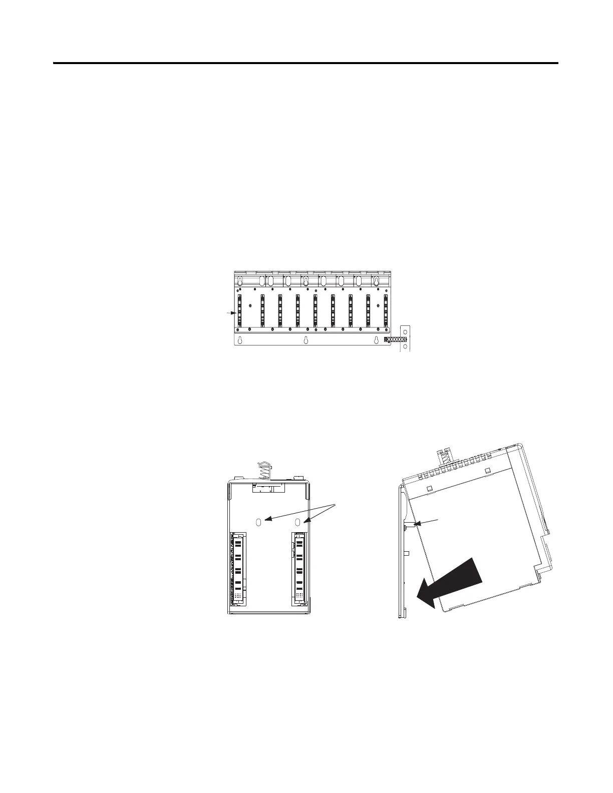
4. Pivot the IAM module
downward, aligning the
guide pins on the power
rail with the guide pin
holes on the back of the
module.
5. Gently push the module
against the power rail.
Guide Pin
Guide
Pin Holes
Power Rail
Typical Rear View of
IAM or AM Module
 Loading...


