Rockwell Automation Publication 2071-UM001E-EN-P - November 2013 125
Interconnect Diagrams Appendix A
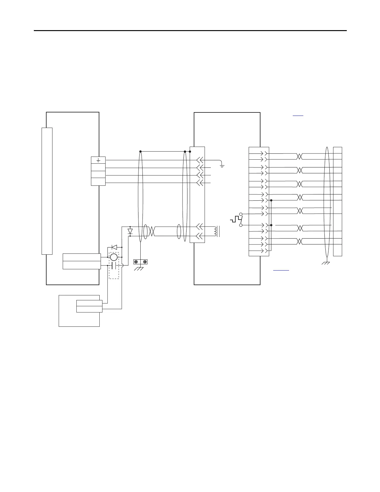
Kinetix 3 Drive/Linear Motor and Actuator Wiring Examples
These wiring diagrams apply to Kinetix 3 drives with compatible actuators and
linear motors.
Figure 52 - Kinetix 3 Drive (230V) Wiring Example with MP-Series
(Bulletin MPAS-A) Linear Stages, LDAT-Series Linear Actuators, and LDC-Series, LDL-Series Linear
Motors
AM+
AM-
BM+
BM-
IM+
IM-
+5VDC
ECOM
BLUE
WHT/BLUE
GREEN
WHT/GREEN
GRAY
WHT/GRAY
BLACK
WHT/BLACK
RED
WHT/RED
3
4
5
6
7
8
20
1
10
TS-
S1
–
TS+
ORANGE
WHT/ORANGE
2
S2
S3
COM
YELLOW
WHT/YELLOW
14
16
3
4
5
6
1
2
14
15
16
17
12
11
13
9
10
D
C
B
A
BR-
BR+
F
G
W
V
U
48
47
GREEN/YELLOW
BLUE
BLACK
BROWN
BLACK
WHITE
GND
SHIELD
W
V
U
0
1
2
3
4
5
6
7
8
9
10
11
12
13
14
15
16
17
18
19
20
CR1
OUTPUT 3- (BK-)
OUTPUT 3+ (BK+)
24V DC
24V DC COM
MPAS-Axxxx-ALMx2C
Linear Stages or
LDC-Series, LDL-Series
Linear Motor
with Incremental Feedback
Motor Brake
Three-phase
Motor Power
Motor
Feedback
I/O (IOD)
Connector
Note 4
Motor Power
(MP) Connector
2071-Axx
Kinetix 3 Drive
Motor Feedback
(MF) Connector
User Supplied
24V DC
Refer to table on page 122 for note information.
2090-XXNPMF-xxSxx (standard)
or 2090-CPBMxDF-xxAFxx
(continuous-flex)
Motor Power Cable
Note 9
Use 2090-CPWMxDF-xxAFxx
cable for continuous-flex non-brake applications.
Refer to Motor Feedback Breakout
Board Installation Instruction
Publication
2071-IN003
for proper grounding
technique.
2090-XXNFMF-Sxx (standard) or
2090-CFBMxDF-CDAFxx (continuous-flex)
(flying-lead) Feedback Cable
Note 9
Cable
Shield
Clamp
Note 7
2071-TBMF
Motor Feedback
Breakout Board

 Loading...


