Programming and Parameters 1-45
UTILITY
Diagnostics
226 [Fault Bus Volts]
Captures and displays the DC bus
voltage of the drive at the time of the last
fault.
Default:
Min/Max:
Units:
Read Only
0.0/Max Bus Volts
0.1 VDC
224
thru
230
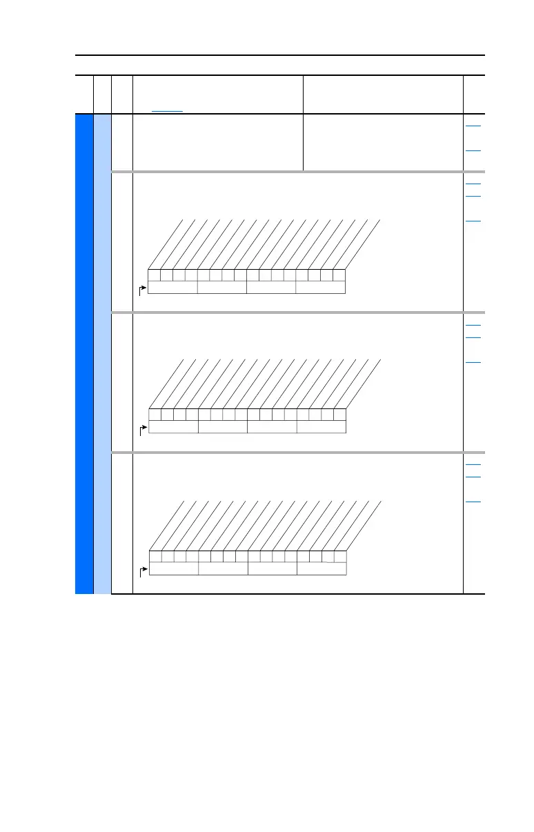
227 [Status 1 @ Fault]
Captures and displays [Drive Status 1] bit pattern at
the time of the last fault.
Read Only 209
224
thru
230
228 [Status 2 @ Fault]
Captures and displays [Drive Status 2] bit pattern at
the time of the last fault.
Read Only 210
224
thru
230
229 [Alarm 1 @ Fault]
Captures and displays [Drive Alarm 1] at the time of
the last fault.
Read Only 211
224
thru
230
File
Group
No.
Parameter Name & Description
See page 1-2 for symbol descriptions
Values
Related
0110000101110000
10 01234567891112131415
1=Condition True
0=Condition False
x =Reserved
Bit #
Ready
Active
Command Dir
Actual Dir
Accelerating
Decelerating
Alarm
Faulted
At Speed
Local ID 0
Local ID 1
Local ID 2
Spd Ref ID 0
Spd Ref ID 1
Spd Ref ID 2
Spd Ref ID 3
00000000000000xx
10 01234567891112131415
1=Condition True
0=Condition False
x =Reserved
Bit #
Ready
Active
Running
Jogging
Stopping
DC Braking
AutoTuning
DB Active *
AutoRst Ctdn
AutoRst Act
Curr Limit
Bus Freq Reg
Motor Overld
DPI at 500 k
* Vector firmware 3.001 & later
000000x00000000x
10 01234567891112131415
1=Condition True
0=Condition False
x =Reserved
Bit #
Prechrg Actv
UnderVoltage
Power Loss
Str At PwrUp
Anlg in Loss
IntDBRes OH
Drv OL Lvl 1
Drv OL Lvl 2
Decel Inhibt
Waking
Motor Therm *
In PhaseLoss *
Load Loss *
Ground Warn *
* Vector firmware 3.001 & later
20B-UM001.book Page 45 Thursday, June 20, 2013 1:55 PM

 Loading...


