Publication 2100-IN012C-EN-P - April 2009 39
Installation Procedures Chapter 2
Joining and Splicing NEMA
Type 12 MCCs
NEMA Type 12 MCCs must be properly installed to prevent the ingress
of dust and dirt. Follow the caulking instructions in the NEMA Type 12
Sealing Instructions, publication 2100-IN037
, supplied with the NEMA
12 MCC. Using caulk, close any mounting holes in the bottom plates
and bolt holes between shipping splits.
It is necessary that all door latches and wireway doors be fully latched
to prevent dust and dirt from entering the enclosure and to meet
NEMA Type 12 requirements.
Joining & Splicing NEMA
Type 3R and Type 4 MCCs
A main horizontal bus, a neutral bus (if required) and a ground bus
splice kit must be installed between the internal sections for new and
existing NEMA Type 3R and Type 4 MCCs. Refer to CENTERLINE 2100
Motor Control Centers Joining & Splicing Vertical Sections Instructions,
publication 2100-IN010
, for splicing Type 3R and Type 4 internal
sections.
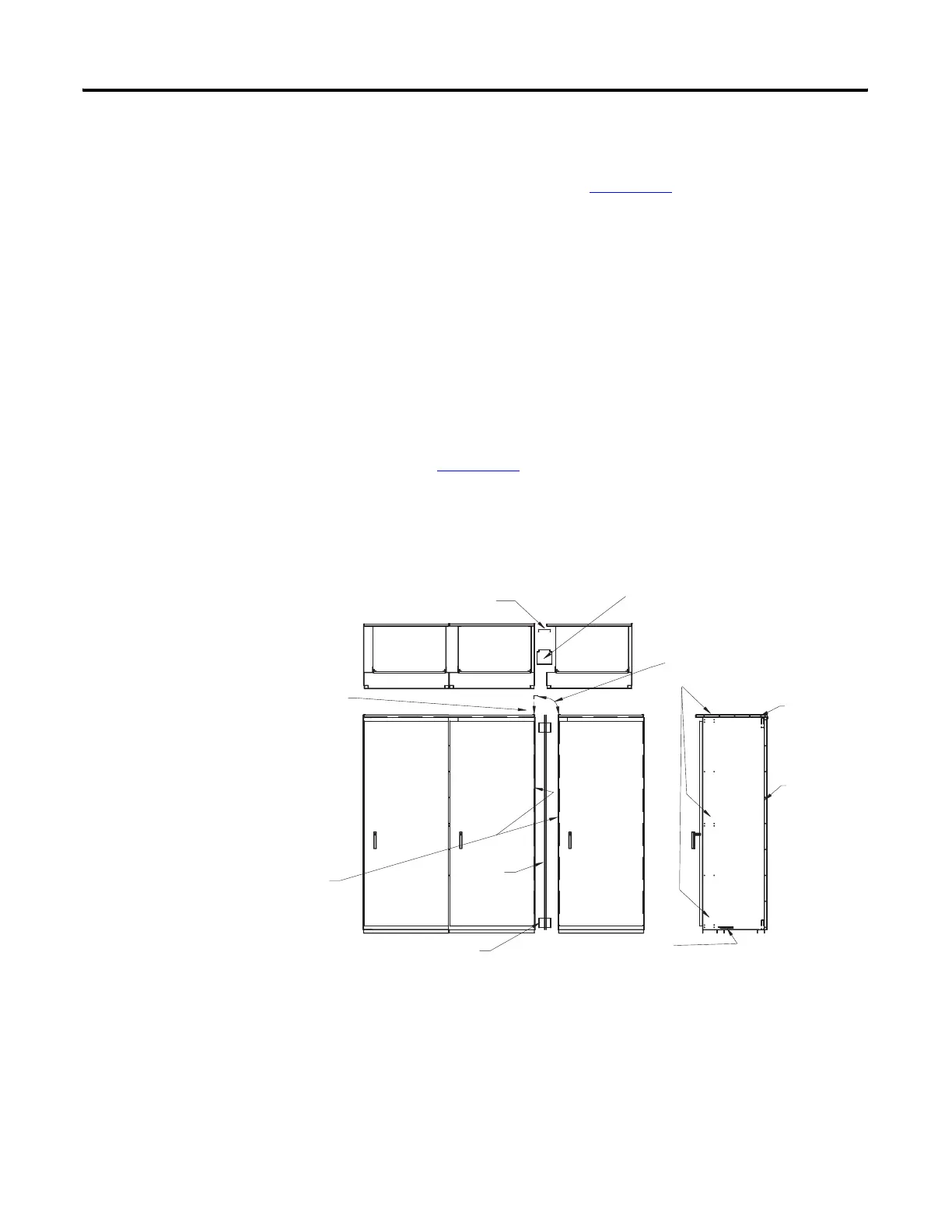
Joining Instructions for NEMA Type 3R and 4 Sections
MCC MCC MCC
Cabinet Spacer
(2) 0.25 in. (6 mm) x 0.50 in. (12.7 mm) Taptites
Cabinet Spacer
(2) 0.25 in. (6 mm) x 0.50 in.
(12.7 mm) Taptites
(2) 0.25 in. (6 mm) x 0.50 in. (12.7 mm) Taptit
Cabinet Spacer
(2) 0.25 in. (6 mm)
0.50 in. (12.7 mm)
Taptites
Gasket
Gasket
Wireway Extensions
(2) or (4) 0.25 in. (6 mm) x 0.50 in.
(12.7 mm) Taptites
(2) wireway extensions required for 15 in. (381 mm) deep.
(2) wireway extensions required for 20 in. (508 mm) deep.
(1) 0.25 in. (6 mm) -20 x 0.70 in. (17.78 mm) taptite per wireway extension.
Remove left-hand driphood angle and remount
after the adjacent driphood has been drilled out.
Remove right-hand driphood angle and
discard. Drill out (5) 0.172 in. (4.36
mm) diameter holes to 0.25 in. (6 mm)
diameter in driphood.
Remove the right-hand and
left-hand side plates before joining
sections. The gasket is across the
top of the driphood and down the
backplate on one of the adjoining
sections.
Gasket
 Loading...