Publication 2100-IN012C-EN-P - April 2009 37
Installation Procedures Chapter 2
Seismic Requirements
To demonstrate the seismic withstand of various CENTERLINE MCCs
[20 in. deep (508 mm), 30 in. deep (762 mm) back-to-back, and 40 in.
deep (1016 mm) back-to-back], the MCC design construction has been
qualified by seismic calculations per the Uniform Building Code
(UBC). CENTERLINE 2100 MCC samples have been seismically
qualified by dynamic (triaxial multi-frequency testing) seismic tests per
IEEE 344 Seismic Test Standards. The results of the MCC seismic
testing demonstrated compliance with the 100% g level of Uniform
Building Code 1997 (UBC) zone 4 (the maximum UBC zone) and
100% g level of The International Building Code 2006 (IBC), for
example, the MCC structure, the MCC units, and the MCC components
or electrical functions were not compromised when subjected to a
UBC Zone 4 earthquake, or the IBC seismic event. Per the IEEE 344
standard, the equipment was under power and operated before,
during, and after the seismic tests.
In order to obtain a UBC or IBC seismic withstandability, each
individual CENTERLINE 2100 MCC lineup (for example, both front
and back MCCs in ‘back-to-back applications), must be mounted on
an adequate seismic foundation and installed per the seismic
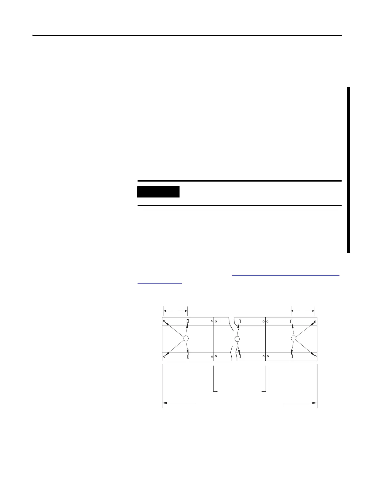
anchoring requirements as shown in the following illustrations.
In seismic application dimensions ‘E’ applies to the first and last
sections of the MCC lineup. See Mounting Dimensions for 15 in. and
20 in. Sections for dimensions.
Seismic Bolt Down Requirements
IMPORTANT
Variable frequency drive units using ‘rollout’ drive
configurations are not seismically tested.
EERear
FrontFirst Section Last Section
Second Section and
Additional Sections
MCC Lineup
1
The hardware required is 1/2 in.-13 Grade 5 or HSL-3 M12 or better bolts embedded in the foundation.
1
1
1
 Loading...