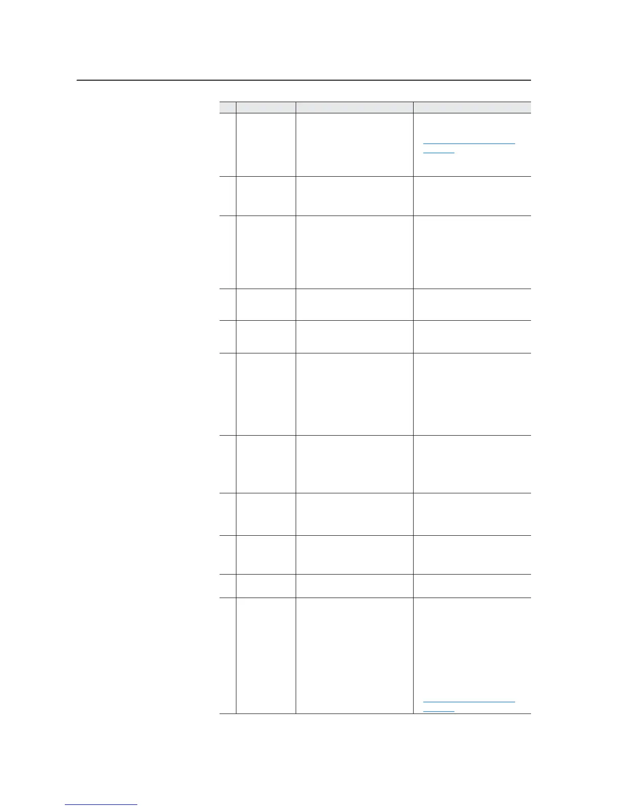
1-14 Troubleshooting and Error Codes
14 InverterFault A hardware problem exists in the
power structure.
1. Cycle the power.
2. Contact Technical Support. See
Technical Support Options on
page 1-19 for more information.
3. If the problem persists, replace the
drive.
15 Load Loss Do not use this fault in 700H
applications
Check that parameter 238 [Fault
Config 1] / bit 0 “Power Loss” and
parameter 259 [Alarm Config 1] / bit
13 “Load Loss” are set to zero.
16 Motor Therm The option board thermistor input is
greater than the limit.
1. Check to ensure that the motor is
cooling properly.
2. Check for an excess load.
3. Verify the thermistor connection. If
the thermistor connection on the
option board is not used, it must be
shorted.
17 Input Phase One input line phase is missing.
Configured in parameter 238 [Fault
Config 1]
1. Check all user-supplied fuses
2. Check the AC input line voltage.
21 OutPhasMissng There is zero current in one of the
output motor phases.
1. Check the motor wiring.
2. Check the motor for an open
phase.
24 Decel Inhibit The drive cannot follow the
commanded decel due to bus
limiting.
1. Verify that the input voltage is
within the specified limits.
2. Verify that the system ground
impedance follows the proper
grounding techniques.
3. Disable bus regulation and/or add
a dynamic brake resistor and/or
extend the deceleration time.
25 OverSpd Limit Functions such as Slip
Compensation or Bus Regulation
have attempted to add an output
frequency adjustment greater than
the value programmed in parameter
83 [Overspeed Limit].
Remove the excessive load or
overhauling conditions or increase
the value in parameter 83
[Overspeed Limit].
28 BrakResMissing No brake resistor has been detected. 1. Program parameter [Bus Reg
Mode x] to not use the brake
option.
2. Install a brake resistor.
29 Anlg In Loss An analog input is configured to fault
on a signal loss. A signal loss has
occurred. Configure this fault with
[Anlg In x Loss].
1. Check parameter settings.
2. Check for broken/loose
connections at the inputs.
30 MicroWatchdog A microprocessor watchdog timeout
has occurred.
1. Cycle the power.
2. Replace the Main Control board.
31 IGBT Temp HW The drive output current has
exceeded the instantaneous current
limit.
1. Check for an excess load.
2. Raise the value set in [Accel Time
x].
3. Parameter 53 [Motor Cntl Sel] may
need to be set to “Custom V/Hz”.
4. Verify the values set in parameters
62 [IR Voltage Drop] and 63 [Flux
Current Ref].
5. Contact Technical Support. See
Technical Support Options on
page 1-19 for more information.
No. Name Description Action (if appropriate)

 Loading...