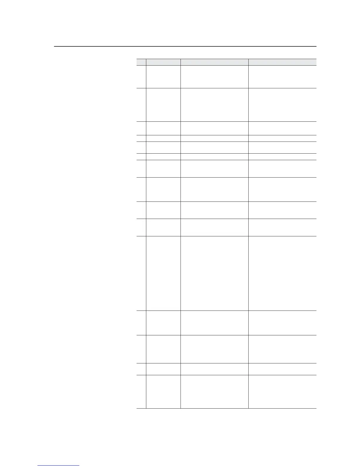
Troubleshooting and Error Codes 1-15
32 Fan Cooling Fan is not energized at start
command.
1. Check the status LEDs on the fan
inverter(s).
2. Verify that the fan(s) and fan
inverter(s) are running.
33 AutoReset Lim The drive unsuccessfully attempted
to reset a fault and resumed running
for the programmed number of [Flt
RstRun Tries]. you can enable/
disable this fault with parameter 238
[Fault Config 1].
Correct the cause and manually clear
the fault.
34 CAN Bus Flt A sent message was not
acknowledged.
1. Cycle the power.
2. Replace the Main Control board.
37 HeatsinkUndTp The ambient temperature is too low. Raise the ambient temperature.
44 Device Change The new power unit or option board
installed is a different type.
Clear the fault and reset the drive to
the factory defaults.
45 Device Add A new option board was added. Clear the fault.
47 NvsReadChksum There was an error reading
parameters 9 [Elapsed MWh] and 10
[Elapsed Run Time] from EEPROM.
1. Cycle the power.
2. Replace the Main Control board.
48 ParamsDefault The drive was commanded to write
default values to EEPROM.
1. Clear the fault or cycle power to
the drive.
2. Program the drive parameters as
needed.
50 MotorCalcData The motor nameplate data is
incorrect.
Check the motor nameplate data and
verify the proper entry in the “Motor
Data” parameters.
54 Zero Divide This event occurred because a
mathematical function had a dividend
of zero.
1. Cycle the power.
2. Replace the main control board.
59 Gate Disable Both of the digital gate disable inputs
(SD-1 and SD-2) are not enabled on
the 20C-DG1 option board.
1. Check the motor.
2. Verify that the option board is
properly wired.
3. Replace the option board. Refer to
Appendix E -“Instructions for ATEX
Approved PowerFlex 700H Drives
in Group II Category (2)
Applications with ATEX Approved
Motors” in the PowerFlex 700H/S
High Power Drives Installation
Manual, publication
PFLEX-IN006… for information on
installing this option board.
60 Hrdwr Therm The thermistor input is activated
(>4kΩ) on the 20C-DG1 option
board.
1. Check the motor.
2. The resistance of the thermistor
input must go below 2kΩ before
the drive can be reset.
63 Shear Pin The value programmed in parameter
148 [Current Lmt Val] has been
exceeded. You can enable/disable
this fault with parameter 238 [Fault
Config 1].
Check the load requirements and the
value in [Current Lmt Val].
65 I/O Removed An I/O option board has been
removed.
Clear the fault.
70 Power Unit One or more of the output transistors
were operating in the active region
instead of desaturation. This can be
caused by excessive transistor
current or insufficient base drive
voltage.
Clear the fault.
No. Name Description Action (if appropriate)

 Loading...