EN
57
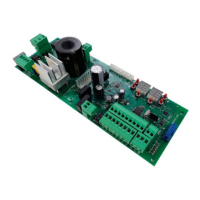
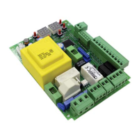
6 Description of connections
To access the control connection terminal board, remove the motor cover as shown in ƼKYVI:
Figure 2-3-4-5 shows connection diagrams for connecting mains voltage to the motor control unit.
6.1 Typical installation
1
7
8
2
2
6
3
3
4
5
It is the installer's responsibility to verify the adequacy of the cables in relation to the
devices used in the installation and their technical characteristics.
Recommended cable
1 Power supply H07RN-F 3x1,5 mm
2
double insulated cable
2 Photocell - Receiver F4ES/F4S Cable 4x0,5 mm
2
(max 20 m)
3 Photocell - Transmitter F4ES/F4S Cable 2x0,5 mm
2
(max 20 m)
4
LED Flashing light R92/LED24 - FIFTHY/24
Power supply 24Vdc
Cable 2x1 mm
2
(max 10 m)
5 Antenna Cable 50 Ohm RG58 (max 10 m)
6
Key selector R85/60 Cable 3x0,5 mm
2
(max 20 m)
Key pad H85/TTD - H85/TDS (connecting to H85/DEC - H85/
DEC2)
Cable 2x0,5 mm
2
(max 30 m)
H85/DEC - H85/DEC2 (connecting to control unit)
Cable 3x0,5 mm
2
(max 20 m)
The number of conductors increases when using more
than one output contact on H85/DEC - H85/DEC2
7
Gate open indicator
Power supply 24V DC 3W max
Cable 2x0,5 mm
2
(max 20 m)
8
Courtesy light (Potential free contact)
Power supply 230 Vac (100 W max)
Cable 2x1 mm
2
(max 20 m)
SUGGESTIONS: with existing installations, we recommend checking the cross section of the cables and that
the cables themselves are in good condition.
 Loading...