EN
59
7 Commands and Accessories
If not installed, safety devices with NC contacts must be jumpered at the COM terminals, or disabled by modifying
the parameters , , , , and .
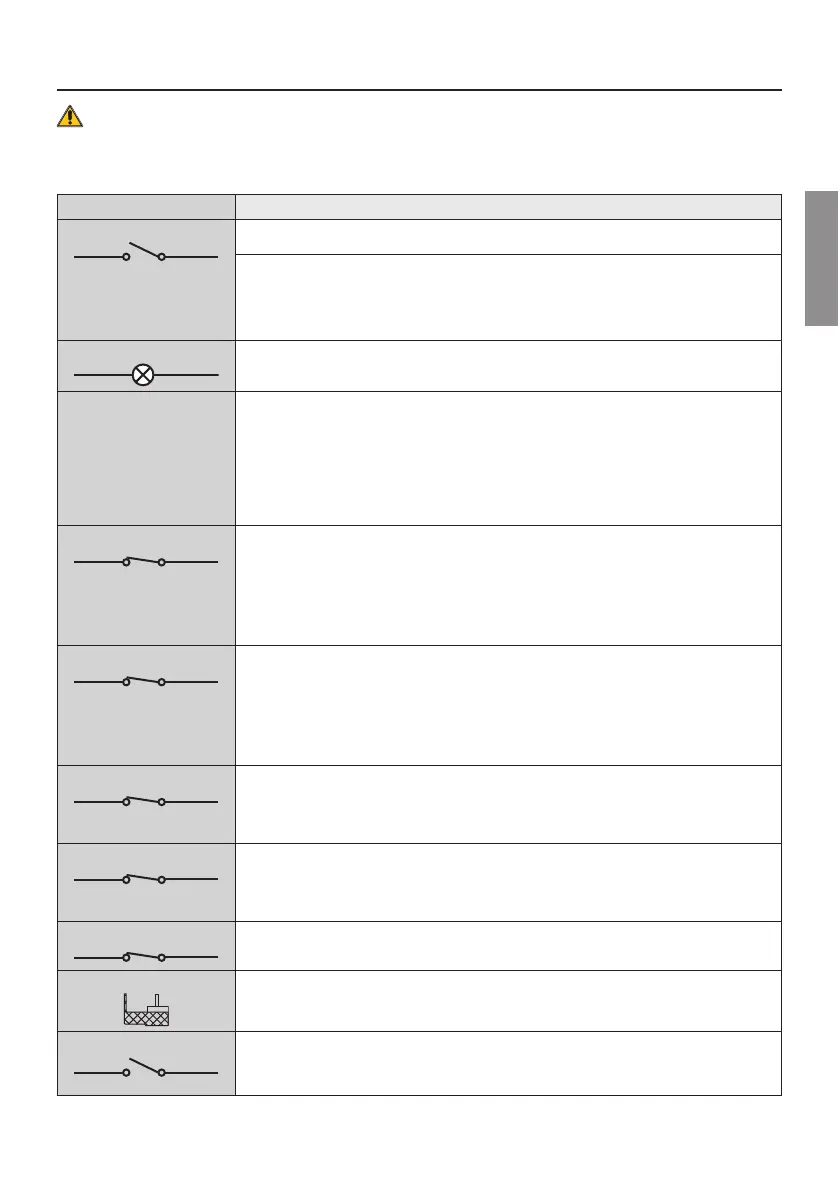
KEY:
N.A. (Normally Open) .
N.C. (Normally Closed).
CONTACT DESCRIPTION
8 9(COR)
Output (potential free contact) for connecting courtesy light. 230 Vac 100 W - 24 Vac/dc 40 W.
NOTE: Provide a protective fuse.
Error alert contact only, for:
• Unlocked gate / battery supply error (low battery);
• +EXIGSQTPIXIP]STIRKEXIGSQTPIXIP]GPSWIHƼK
The COR output operating mode is managed by parameter .
The voltage level of the battery can be set via parameter .
10(+SC) 11(COM)
Connection for gate open indicator lamp. 24 Vdc 3 W.
The function of the indicator lamp is determined by parameter $.
10(+SC) 11(COM)
Photocell test connection and/or battery saving.
8LITS[IVJIIHJSVXLITLSXSGIPPXVERWQMXXIVW8<QE]FIGSRRIGXIHXS10(+SC).
Set the parameter $ to enable the test function.
Each time a command is received, the control unit switches the photocells off and on to check that
the contact changes state correctly.
Power feeds for all external devices may be connected to reduce battery consumption (if batteries
are used). Set $ or $ .
WARNING! If contact 10(+SC) is used for the photocell test function or battery saving function, a
gate open indicator lamp cannot be connected.
12(FT2) 30(COM)
Input (NC) for connecting photocells FT2ƼK
The photocells FT2 EVIGSRƼKYVIHF]HIJEYPX[MXLXLIJSPPS[MRKWIXXMRKW
– . Photocell FT2 disabled when gate is opening.
– . Photocell FT2 disabled when gate is closing.
– . The gate opens when an open command is received if photocell FT2 is obstructed.
If the photocells are not installed, jumper the terminals 30(COM) - 12(FT2) or set the parameters
and .
WARNING! Use F4ES or F4S series photocells.
13(FT1) 30(COM)
Input (NC) for connecting photocells FT1ƼK
The photocells FT1 EVIGSRƼKYVIHF]HIJEYPX[MXLXLIJSPPS[MRKWIXXMRKW
– . Photocell triggers only during gate closure. Photocell is ignored during gate opening.
– . Movement is reversed if the photocell is triggered during gate closure.
– . The gate opens when an open command is received if photocell FT1 is obstructed.
If the photocells are not installed, jumper the terminals 30(COM) - 13(FT1) or set the parameters
and .
WARNING! Use F4ES or F4S series photocells.
14(COS2) 16(COM)
Input (NC or 8 kOhm) for connecting sensing edge COS2.
8LIWIRWMRKIHKIMWGSRƼKYVIHF]HIJEYPX[MXLXLIJSPPS[MRKWIXXMRKW
– . The sensing edge COS2 (NC contact) is disabled.
If the sensing edge is not installed, jumper the terminals 14(COS2) - 16(COM) or set the parameter
.
15(COS1) 16(COM)
Input (NC or 8 kOhm) for connecting sensing edge COS1.
8LIWIRWMRKIHKIMWGSRƼKYVIHF]HIJEYPX[MXLXLIJSPPS[MRKWIXXMRKW
– . The sensing edge COS1 (NC contact) is disabled.
If the sensing edge is not installed, jumper the terminals 15(COS1) - 16(COM) or set the parameter
.
17(ST) 16(COM)
STOP command input (NC).
The current manoeuvre is arrested if the safety contact opens.
N.B.: the controller is supplied with this contact already jumpered by ROGER TECHNOLOGY.
22 21(ANT)
Antenna connector for slot-in radio receiver board.
Use RG58 if an external antenna is used; maximum recommended length: 10 m.
N.B.: do not make joints in cable.
24(ORO) 23(COM)
Clock timer contact input (N.O.).
When the clock function is active, the gate opens and remains open. At the end of the programmed
time set with the external device (clock), the gate closes.
The function of this command is determined by parameter .
 Loading...