Do you have a question about the Roland OCTAPAD SPD-30 and is the answer not in the manual?
| Product color | Black, Grey |
|---|---|
| Sound effects | Yes |
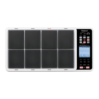
| Number of pads | 8 |
| Drum kits quantity | 50 |
| Instrument sounds quantity | 670 |
| Display type | LCD |
| Display resolution | 160 x 160 pixels |
| USB connector type | USB Type-A, USB Type-B |
| Headphone connectivity | 6.3 mm |
| 6.35 mm (1⁄4-inch) input | 5 |
| 6.35 mm (1⁄4-inch) output | 2 |
| Power source type | AC |
| Depth | 272 mm |
|---|---|
| Width | 541 mm |
| Height | 88 mm |
| Weight | 3800 g |
Important preliminary notes before performing procedures.
Procedure to back up user settings before maintenance.
Instructions for replacing components, especially near heat circuits.
Criteria for parts not being supplied as service parts.
Explanation of abbreviations like NIU and UnPop in diagrams.
Details about the serial number and voltage code.
Details on built-in and external pad connections.
Information on the number of kits and kit chain parameters.
Parameters for tuning, muffling, tone color, pitch, etc.
List of available effect types like Ambience, EQ, Limiter.
Details on phrases, parts, tempo, and resolution.
LCD type, pad illumination, and input/output jack details.
Technical specs for output impedance, physical size, and weight.
List of standard accessories and available optional products.
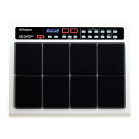
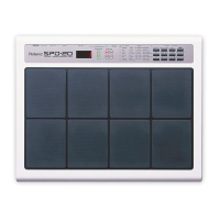
Visual identification of unit controls and ports.
Part codes and names for external controls and connectors.
Top/front view of the unit with labeled controls.
Bottom view of the unit with labeled mounting points.
Internal view showing component layout and wiring.
Internal view showing structural elements and mounting.
Rear panel view with labeled connectors.
Step-by-step instructions to remove the bottom case.
Step-by-step instructions to reattach the bottom case.
Instructions for correctly bending flat cables for connection.
Procedures for installing gasket and LED lens components.
Steps for installing springs to the LED board.
How to attach the LED cushion to the panel board correctly.
Procedures for attaching dust covers to boards.
Steps for installing dust covers and display cushion for LCD.
Instructions for applying tape to the panel board underside.
Steps for assembling the LCD screen and connecting cables.
How to insert connectors onto the Jack Board Assy.
Routing and securing sensor cables to the unit.
Steps to format USB storage for data backup.
Procedures for saving and loading user settings.
Preparing the USB drive for system updates.
Steps to perform the system update on the unit.
How to access the service test mode.
How to exit the service test mode.
Navigation within the test mode.
Overview of available diagnostic tests.
Verifying system version information.
Checking MIDI input/output functionality.
Testing unit buttons and indicator lights.
Testing rotary encoder functionality.
Verifying LCD display and backlight operation.
Testing the Hi-Hat control input.
Testing foot switch inputs.
Testing pad and external trigger response.
Testing the cancel sensor function.
Testing audio input/output signals.
Verifying audio output silencing.
Checking internal device operations.
Playing back the internal demo song.
Performing factory reset as a test.
Schematics for LED boards.
Schematics for the panel board.
Schematics for the jack board.
Schematic for the LED-A board.
Schematic for the LED-B board.
Schematic for the LED-C board.
Schematic for the LED-D board.