2
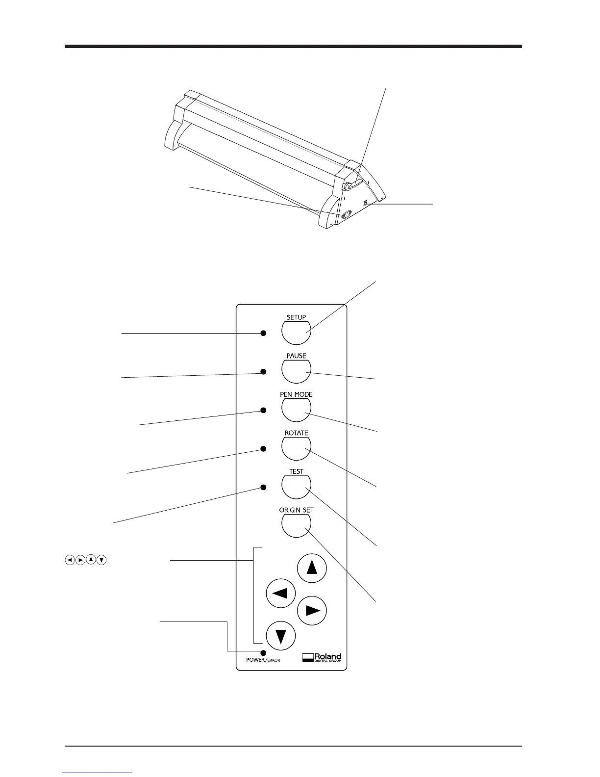
2-2 Rear View
2-3 Operation Panel
Power Connector (AC IN)
This connector accepts standard AC
power cord.
Sheet Loading Lever
This moves the pinch rollers up and
down to load and release the material.
Power Switch
ON when switched to [I].
OFF when switched to [O].
* The TEST key and the position keys function only
when the SETUP LED is lighted, and the ROTATE key
functions only when the SETUP LED is not lit.
2 Part Names and Functions
SETUP Key
Press this to detect the width of the loaded
material and enable the unit for cutting.
Pressing this while operation is paused deletes
the data sent from the computer.
PAUSE Key
When pressed once, this temporarily halts
cutting in progress. Pressing this key again
releases the paused state.
PEN MODE Key
Press this to perform plotting with a pen on
paper. (Be sure to load a pen in the tool
carriage.)
ROTATE Key
Pressing this key sets the origin point at the
bottom right of the material and rotates the
direction of cutting by 90°.
TEST Key
This performs a cutting test to check whether
blade force is correct.
ORIGIN SET Key
This sets the origin point for cutting to the
current tool position.
(Position Keys)
These are used to move the material or the tool
carriage.
SETUP LED
This lights up when the SETUP key is pressed.
Cutting can be performed when this is lit.
PAUSE LED
This lights up when the PAUSE key is pressed to
pause the PNC-960/910.
PEN MODE LED
This lights up when the PEN MODE key is
pressed.
ROTATE LED
This lights up when the ROTATE key has been
pressed.
TEST LED
This lights up when the TEST key is pressed.
POWER/ERROR LED
This lights up when the power is switched on,
and flashes when an error is generated.
The PEN MODE LED and POWER/ERROR LED blink simultaneously.
This flashes if the location of the pinch rollers is not correct, if DIP switch SW-9 on the PNC-960 is set to ON (piece material) and material
with a vertical length of 100 mm (3-15/16") or less has been loaded, or if SW-9 is set to ON and there is no material over the front and rear paper sensors.
For more details, see "3-4 Loading/Removing the Material".
 Loading...