MODEL SOLU COMP II SECTION 8.0
TROUBLESHOOTING
3. Connect a jumper wire between the RTD RETURN and RTD SENSE terminals (see wiring diagrams in
Section 3.2). Connect a second jumper wire between the REFERENCE IN and SOLUTION GROUND ter-
minals.
4. If noise and/or offsets disappear, the interference was coming into the analyzer through one of the sensor
wires. The system can be operated permanently with the simplified wiring.
D. Check for extra ground connections or induced noise.
1. If the sensor cable is run inside conduit, there may be a short between the cable and the conduit. Re-run
the cable outside the conduit. If symptoms disappear, there is a short between the cable and the conduit.
Likely a shield is exposed and touching the conduit. Repair the cable and reinstall it in the conduit.
2. To avoid induced noise in the sensor cable, run it as far away as possible from power cables, relays, and
electric motors. Keep sensor wiring out of crowded panels and cable trays.
3. If ground loops persist, consult the factory. A visit from an experienced technician may be required to solve
the problem.
8.3.8 Current Output Too Low.
Load resistance is too high. Maximum load is 600 Ω.
8.3.9 Alarm Relays Do Not Work
A. Verify the relays are properly wired.
B. Replace power supply PCB (PN 23818-00)
8.3.10 Display is Unreadable.
While holding down the MENU key, press " or ' until the display has the correct contrast.
8.4 SIMULATING INPUTS
8.4.1 General
This section describes how to simulate a pH input into the Solu Comp analyzer. To simulate a pH measurement,
connect a standard millivolt source to the transmitter. If the transmitter is working properly, it will accurately meas-
ure the input voltage and convert it to pH. Although the general procedure is the same, the wiring details depend
on the location of the preamplifier.
8.4.2 Simulating pH input when the preamplifier is in the
analyzer.
1. Turn off automatic temperature correction and solution temper-
ature correction. From the Program menu, choose Temp. Then
choose Live/Manual and enter 25°C. See Section 5.6 for
details.
2. Disconnect the sensor and connect a jumper wire between the
pH IN and REFERENCE IN terminals.
3. From the display menu choose the pH/temperature/mV screen.
The measured voltage should be 0 mV and the pH should be
7.00. Because calibration data stored in the analyzer may be
offsetting the input voltage, the displayed pH may not be exact-
ly 7.00.
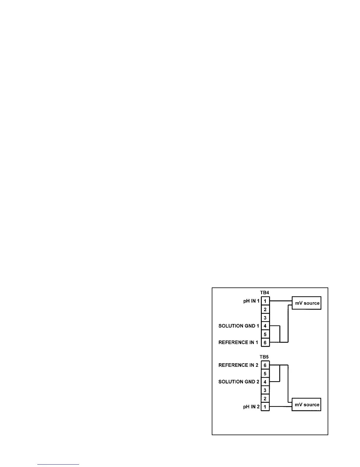
4. If a standard millivolt source is available, disconnect the jumper
wire between pH IN and REFERENCE IN and connect the volt-
age source as shown in Figure 8-1. Be sure to jumper the ref-
erence and solution ground terminals.
FIGURE 8-1. Simulating Inputs When
the Preamplifier is in the Analyzer
45