25
9. Installation & Setup – All CMA Units
9.1.7 Installation Wiring
Route cabling through the most appropriate conduit entry
making sure that cables will not foul on the cover assembly
or internal components after refitting. Refer to the actuator
wiring diagram for connection details.
Wire type must meet local and certifying agency (CSA, IEC Ex,
ATEX, etc) requirements and have a minimum temperature
rating of 88 °C.
Terminate the power, control and indication wiring with
appropriate ferrules. Connect wiring to the terminal block
connectors. Ferrules for power connector must be Phoenix
Contact AI 2,5 - 8 or AI 1,5 - 8 series ferrules or equivalent
with a temperature range of -40 to +105
º
C, a minimum
current rating of 5 A across the temperature range and
approved for field wiring purposes. Take care to route the
wiring away from the spigot housing on the gearcase.
NOTE: RIRO Option.
For ease of wiring the use of 18 AWG wire for remote control
and indication connections is recommended.
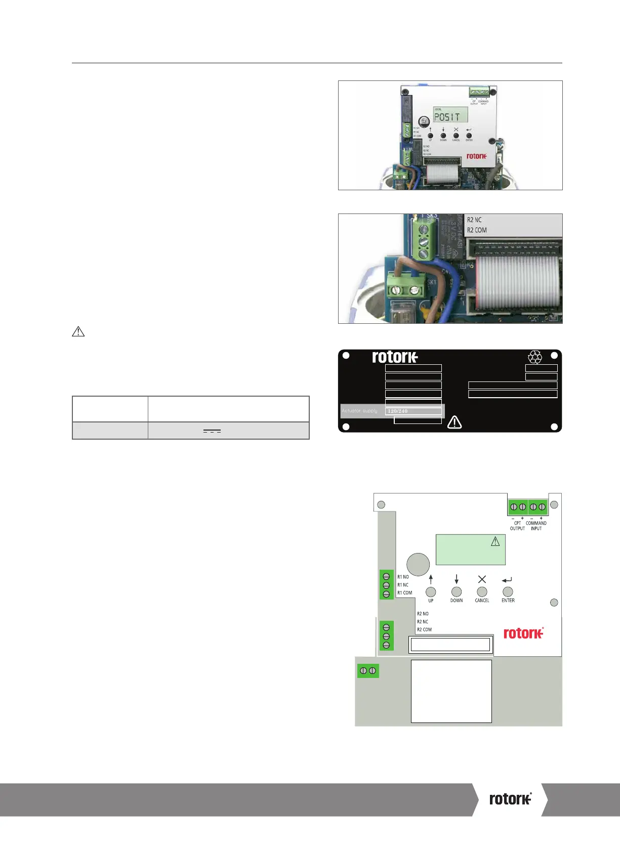
WARNING: The actuator must be checked to ensure
that the voltage specified on the actuator identification
nameplate matches the supply voltage.
CMA is configured at the factory for use with one of the
following power supply voltages:
Single-Phase
50 Hz / 60 Hz
110, 115, 120, 208, 220, 230, 240 VAC
DC 24 VDC Only
Supply voltage fluctuations not to exceed +/- 10% of the nominal supply voltage.
Supply frequency tolerance +/- 10%.
9.1.8 Fuses
Fuse is a 5 x 20, slow acting, glass type with a 250 volt rating.
Use only a 1 amp fuse for AC units and a 2.5 amp device for
DC units.
9.1.9 Relays
Each relay features Normally Open (N/O) and Normally Closed
(N/C) volt-free contacts. Due to the constraints of the Low
Voltage Directive, the maximum allowable voltage that can
be applied to the relay terminals is 150 VAC. For DC however,
the maximum voltage that can be applied is 30 VDC.
Rated Current is 3 A.
9.1.10 CPT Feedback
The Loop-powered transmitter provides 4 to 20 mA signal that
corresponds to position. Loop supply is 24 VDC nominal
(18-30 VDC max).
9.1.11 Demand
The 4-20 mA command signal is used to control actuator
position.
Relay1:
N/O
N/C
Common
Relay2:
N/O
N/C
Common
POS
I
T
REMOTE
Note: Current Position Transmitter (CPT )isloop powered.
CPT Feedback-
CPT Feedback+
Demand -
Demand +
MainsInput
LN
Neutral
Live
(Earth stud
behind)
Serial number
Wiring diagram
Actuator type
Output max.
Enclosure
Actuator supply
Rated current
www.
.com
ROTORK PROCESS CONTROLS
MILWAUKEE, WI, USA.
Unit weight
Year of manufacture
Kg
Amp
IP67
M00-00
M1895423942
CML-250
2224 N
120/240
1
2012
8
Fig 9.9
Fig 9.10
Fig 9.11 Actuator identification label
Fig 9.12 Main PCB
A4 US
US
A4
US
A4
A4 US
 Loading...


