Installation & Maintenance Instructions
26
10. Basic Setup
10.1 Basic Setup
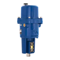
Basic setup is required once the actuator has been mounted
on to the valve.
Procedures include:
Step 1 Select Local Operation
Step 2 Set Output Torque/Thrust
Step 3 Select Action at End of Travel ( Limit or Force)
Step 4 Set Close Limit of Travel
Step 5 Set Open Limit of Travel
Step 6 Calibrate Command Signal Zero Setpoint
Step 7 Calibrate Command Signal Span Setpoint
The Basic Setup procedure is carried out by using the 4
pushbutton switches mounted below the LCD display on the
main PCB.
NOTE: SETTINGS CAN ONLY BE CHANGED WITH THE
ACTUATOR SET TO LOCAL OPERATION.
SW1
‘UP’
SW2
DOWN
SW3
CANCEL
SW4
ENTER
POS
I
T
LOCAL
Fig 10.1
A4US
US
A4
US A4
US
A4
 Loading...


