29
10. Basic Setup
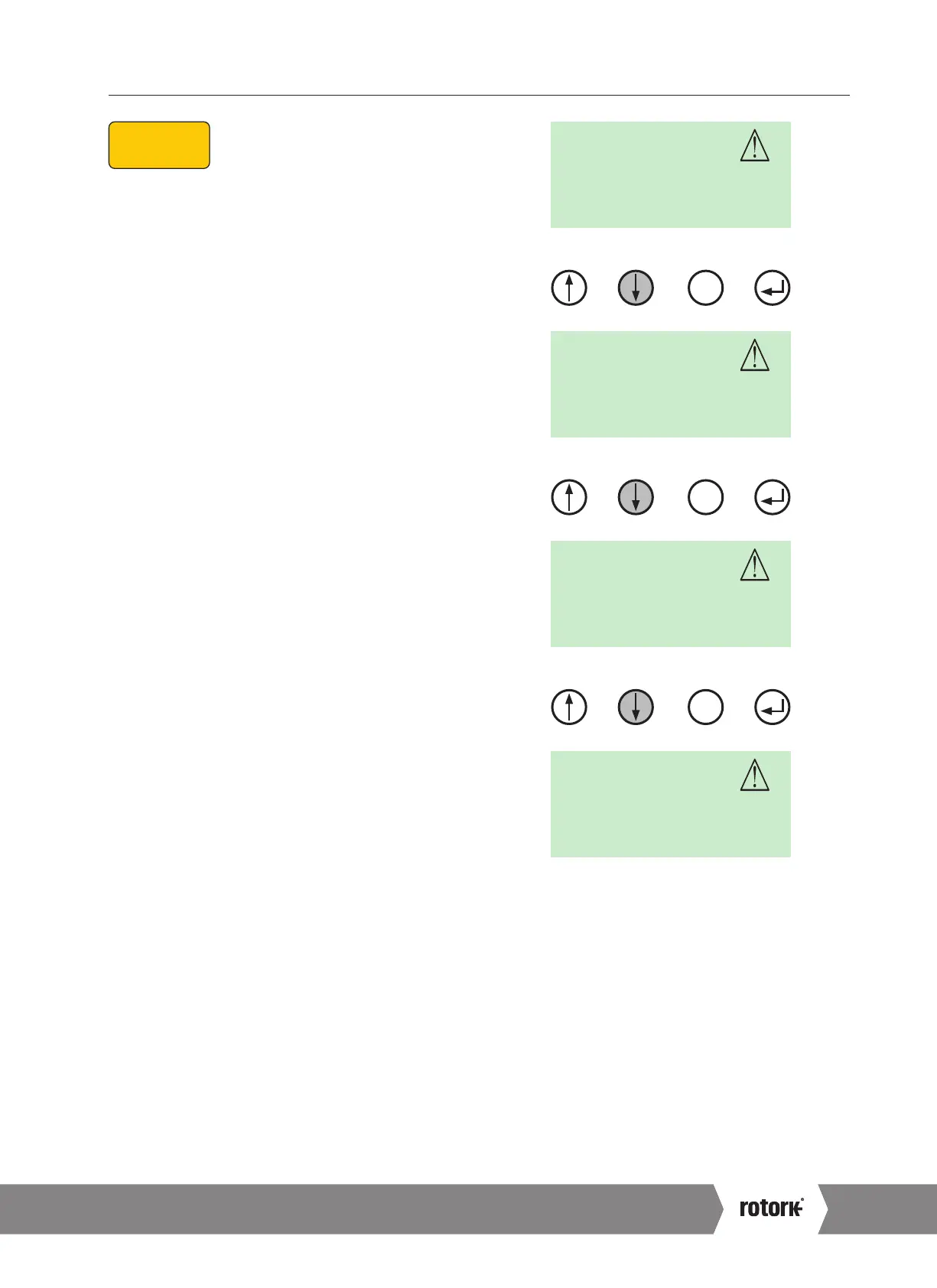
10.4 Select Local Operation
Screen shows the actuator set to Remote operation mode
with alarms active. The actuator must be set to Local
operation mode before the travel limits can be set.
Using the 4 push button switches mounted below the LCD.
PRESS ‘DOWN’
SETPOINT parameter is now displayed.
Press ENTER to view the current setpoint if required.
PRESS ‘DOWN’
THRUST or TORQUE parameter is now displayed depending
on actuator type CML, CMQ, CMR.
Press ENTER to view current Thrust or Torque output value.
If these settings are correct and do not require adjustment
move on to step 4 to set the close limit.
LOCAL/REMOTE parameter is now displayed.
POS
I
T
REMOTE
SET PT
REMOTE
THRUST
REMOTE
X
X
LOCREM
REMOTE
X
STEP 1
SELECT LOCAL
OPERATION
STEP 2
SET OUTPUT
TORQUE/THRUST
STEP 4
SET CLOSE LIMIT
OF TRAVEL
STEP 5
SET OPEN LIMIT
OF TRAVEL
STEP 6
CALIBRATE COMMAND
SIGNAL ZERO SETPOINT
STEP 7
CALIBRATE COMMAND
SIGNAL SPAN SETPOINT
STEP 3
SELECT ACTION AT END
OF TRAVEL ( LIMIT OR FORCE)
STEP 8
DEADBAND
Fig 10.2
Fig 10.3
Fig 10.4
Fig 10.5
A4 US
US
A4
US
A4
A4 US
 Loading...


