Installation & Maintenance Instructions
8
3. Approvals
3.4 Special Conditions For Safe Use (ATEX & IECEx approved actuators)
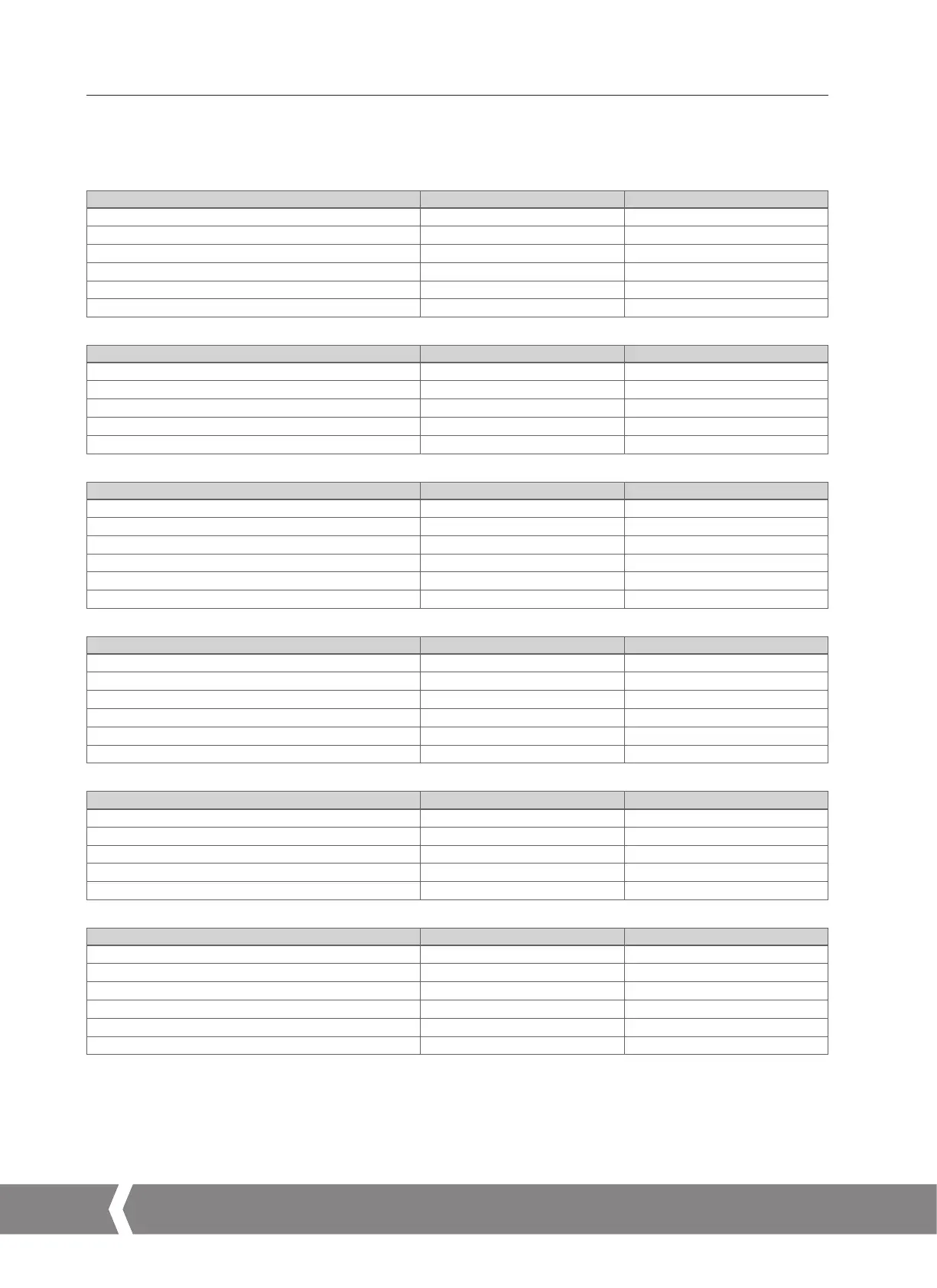
In accordance with clause 5.1 of IEC/EN 60079-1, the critical dimensions of the flamepaths are:
CML-100/250
Flamepath Maximum Gap (mm) Maximum Width L (mm)
Lid/base 0.15 12.8
Base/screw shaft 0.145
¹ 13.5
Base/feedback shaft bush -0.02
² 13.7
Feedback shaft bush/feedback shaft 0.06 13.7
Handknob shaft/lid (short cover) 0.10 25.9
Handknob shaft/lid (intermediate and extended covers) 0.10 15.7
CMR-50/100/200
Flamepath Maximum Gap (mm) Maximum Width L (mm)
Lid/base 0.15 12.8
Base/pinion shaft 0.235
¹ 29.8
Base/output shaft 0.145
¹ 12.8
Handknob shaft/lid (short cover) 0.10 25.9
Handknob shaft/lid (intermediate and extended covers) 0.10 15.7
CMQ-250/500
Flamepath Maximum Gap (mm) Maximum Width L (mm)
Lid/base 0.15 12.8
Base/pinion shaft 0.235
¹ 29.8
Base/feedback shaft bush -0.02
² 13.7
Feedback shaft bush/feedback shaft 0.06 13.7
Handknob shaft/lid (short cover) 0.10 25.9
Handknob shaft/lid (intermediate and extended covers) 0.10 15.7
CML-750
Flamepath Maximum Gap (mm) Maximum Width L (mm)
Lid/base 0.15 12.8
Base/pinion shaft 0.235
¹ 37.3
Base/feedback shaft bush -0.02
² 13.7
Feedback shaft bush/feedback shaft 0.06 13.7
Handknob shaft/lid (short cover) 0.10 25.9
Handknob shaft/lid (intermediate and extended covers) 0.10 15.7
CMR-89/125/250
Flamepath Maximum Gap (mm) Maximum Width L (mm)
Lid/base 0.15 12.8
Base/pinion shaft 0.235
¹ 37.3
Base/output shaft 0.145
¹ 13.0
Handknob shaft/lid (short cover) 0.10 25.9
Handknob shaft/lid (intermediate and extended covers) 0.10 15.7
CMQ-1000
Flamepath Maximum Gap (mm) Maximum Width L (mm)
Lid/base 0.15 12.8
Base/pinion shaft 0.235
¹ 37.3
Base/feedback shaft bush -0.02
² 13.7
Feedback shaft bush/feedback shaft 0.06 13.7
Handknob shaft/lid (short cover) 0.10 25.9
Handknob shaft/lid (intermediate and extended covers) 0.10 15.7
Note 1: This dimension includes an allowance for the 0.05mm requirements defined in clause 8.1.2 of IEC 60079-1:2014.
Note 2: Negative Sign denotes an interference fit.
A4US
US
A4
US A4
US
A4

 Loading...

