Maintenance
4-16
HP6A Manual
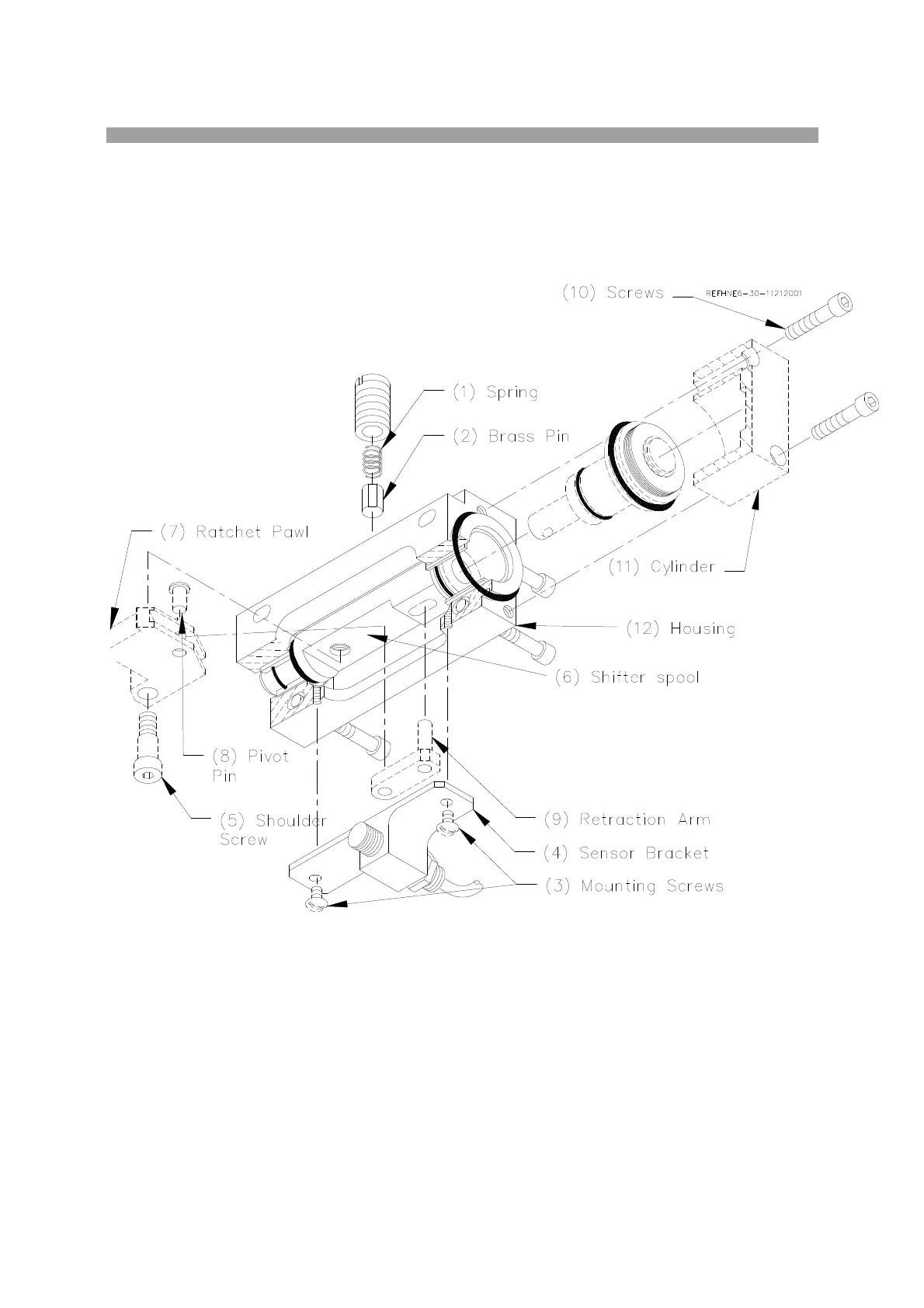
Remove the two screws (3) and the Sensor Mounting Bracket (4) (514-6-80A). Remove the shoulder
screw (5) (514-7-32) from the shifter spool (6) (514-7-26). Pivot the ratchet pawl (7) (514-7-29) out and
remove the pivot pin (8) (514-7-31). Remove the ratchet pawl. Pivot the retraction arm (9) (514-7-30)
back inline with the spool. Lift the retraction arm straight out through the slot in the housing. Remove the
three screws (10) securing the cylinder (11) (514-7-28) to the housing (12).
Once the cylinder is removed the piston (514-7-27A), and the shifting spool (514-7-26) can be pulled out
from the end.
Reassemble is the reverse. The drag pin assembly should be tightened until spring is fully compressed,
then loosen approximately 1/8 turn. Reassemble the auto feed housing onto the ratchet gear cage, the
upper gear housing must be removed so the ratchet pawl can be seen while being assembled, and the
spring loaded ratchet pawl can be attached.
Adjust the engagement of the pawl to the ratchet wheel by loosening the auto feed housing mounting
screws, and moving the housing sideways. Ratchet pawl must just miss one ratchet tooth then fully
engage the next.
 Loading...