Maintenance
4-33
HP6A Manual
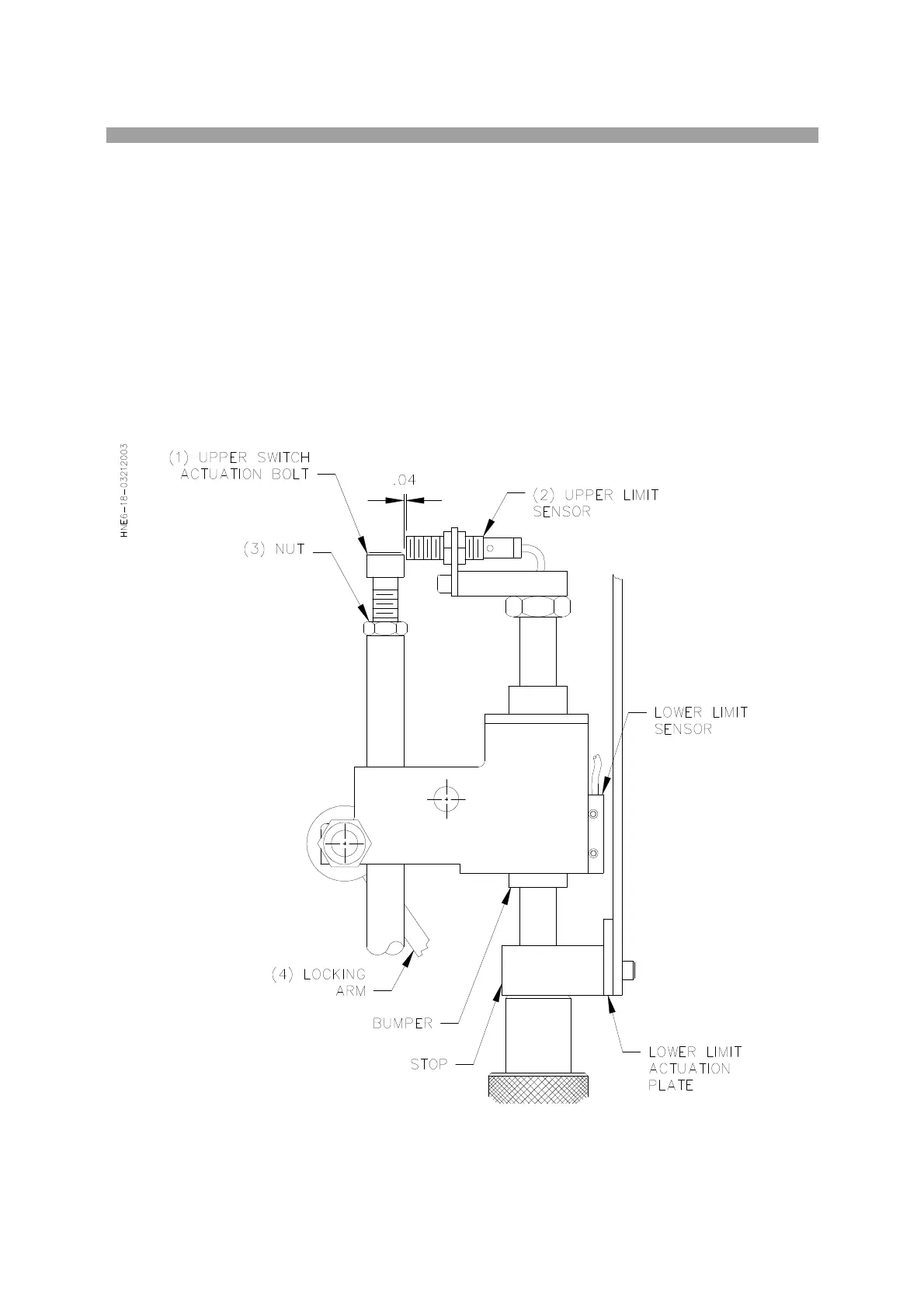
Upper Limit Switch Adjustment:
1) Engage e-stop button so that control panel is not active.
2) Leave main air on the machine. This will keep the Stroking Cylinder Rod in the full up position.
The Stroking Cylinder Rod must be in the full up position for accurate adjustment.
3) Remove the cover from the Rocker Arm (refer to page 6.5 part number 514-6-24F). There are
two screws at the front and rear of this cover.
4) Move the lower stop down so the bolt (1) and sensor (2) can be seen above the Rocker Arm
when it is brought down to the lower stop.
5) Adjust the sensor gap to the bolt, to .04 inches by loosening the two Allen bolts at the rear of the
sensor.
6) Loosen the Locking Nut (3) and start turning the Adjustment Bolt (1) CW until the light on the
sensor goes off. If the light is already off, go to step 7.
7) Start turning the Adjustment Bolt in a CCW direction until the light on the sensor comes on. Once
the light is on turn the Adjustment Bolt another 3 turns and lock the Nut (3)