SERVICE 7
9
WARNING
!
When replacement parts are required, use gen-
uine RYAN parts or parts with equivalent char-
acteristics including type, strength and mate-
rial. Failure to do so may result in product mal-
function and possible injury to operator and/or
bystanders.
Any warning decal that becomes illegible
should be replaced immediately.
Do not operate unit without shields in place.
Do not make any adjustments or perform any
maintenance while the engine is running.
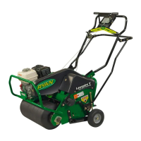
7.1 GENERAL MAINTENANCE
To keep the Greensaire 24 in good operating condition,
the following procedures should be routinely performed.
• Lubricate as recommended in page 27.
• Change engine oil according to engine manual.
Daily, before use:
√ Check oil levels in the crankcase, gear reduction
case and cam case while unit is in raised position.
√ Check for loose screws and connections.
√ Check roller chain tension.
√ Check condition of tines.
√ Check for proper tire pressure.
√ After every use, wash unit with water.
NOTE: Do not wash hot engine with cold water. Dam-
age may result.
7.2 TIRE PRESSURE
Keep tires inflated to recommended pressure.
Tires:
Front 11 x 4.00–5. . . . . . . . . . . . . . . . . . . . . . . . . . . . . . .
Rear 13 x 6.50–6. . . . . . . . . . . . . . . . . . . . . . . . . . . . . .
Pressure 14 to 16 PSI (97 to 110 kPa). . . . . . . . . . . . .
NOTE: Improper inflation will shorten tire life con-
siderably.
CAUTION
!
Check pressure in a partially inflated tire
BEFORE connecting air hose. Due to low air
volume requirements of small tires, over infla-
tion may occur in a matter of two or three
seconds. Over inflation may cause tire to
explode.
7.3 ADJUSTMENTS
Chain Adjustments
Remove shields to provide access to chain drives on
both sides of unit.
Aerator chain idlers (Item 1 in FIGURE 6 and
FIGURE 7) are spring loaded and need no adjustment.
Springs should be routinely checked to be sure they are
hooked.
Drive chain idlers (Item 2 in FIGURE 6 and FIGURE 7)
are adjustable. Chain tension should be routinely
checked and adjusted if necessary.
To adjust idlers:
1. Loosen the nut securing idler sprocket to bracket.
2. Slide the idler sprocket along slot in bracket until
proper chain tension is reached.
Chain deflection opposite idler sprocket should be
1/4”(6mm) max. to 1/8”(3mm) min.
NOTE: Proper chain tension is essential. A tight chain
will cause excessive bearing load. A loose chain will
cause noisy operation and chain pulsations, which
result in irregular sprocket speed and abnormal
chain and sprocket wear.
3. Tighten idler sprocket hardware.
4. Lubricate fittings and roller chains according to
lubrication instructions on page 27.
5. Replace all shields before operating unit.