7 SERVICE
16
7.9 TIMING, CRANKSHAFT & CAMSHAFT
NOTE: Improper timing between the aerating crank-
shaft and the camshaft will cause elongated holes
while aerating and excessive noise in the camcase.
To set timing:
1. Remove shields.
2. Remove chains connecting camshaft and crankshaft
on both sides of unit.
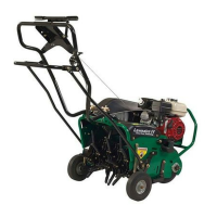
3. Loosen center stud in crankshaft. (See
FIGURE 16.)
3790
1
2
FIGURE 16
1. Aerator Crankshaft
2. Center Stud
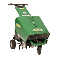
4. Position right camshaft sprocket so that the first
tooth to the right of the timing mark points to the cen-
ter rib of the clutch bracket. Keyway should be level
and point straight forward. (See FIGURE 17.)
Rotation
Front of Unit
Timing mark
Center
Rib of
Clutch
Bracket
FIGURE 17
Camshaft Sprocket, Right Side Of Unit
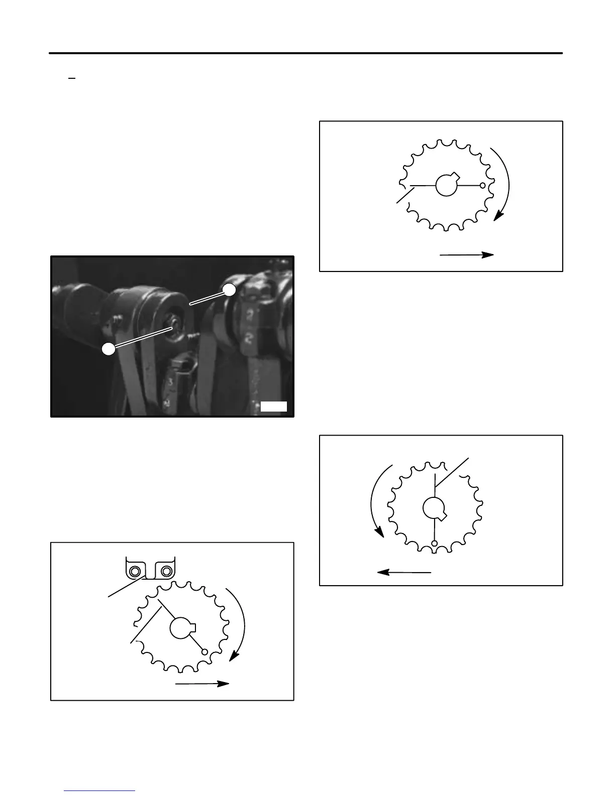
5. Position right crankshaft sprocket so that timing
mark is horizontal. Keyway should be 45° clockwise
from straight up. (See FIGURE 18.)
Rotation
Front of Unit
Timing mark
FIGURE 18
Crankshaft Sprocket, Right Side Of Unit
6. Reinstall chain on camshaft and crankshaft sprock-
ets on right side of unit. Crankshaft may be rotated
clockwise only (Approximately 5°) to properly mesh
with chain.
7. Position left crankshaft sprocket so that timing mark
is vertical. Keyway should be 45° counterclockwise
from straight down. (See FIGURE 19.)
Rotation
Front of Unit
Timing mark
FIGURE 19
Crankshaft Sprocket, Left Side Of Unit
8. Reinstall chain on camshaft and crankshaft sprock-
ets on left side of unit. Crankshaft may be rotated
counterclockwise only (approximately 5°) to properly
mesh with chain.
9. Tighten center stud in crankshaft.
10. Replace all shields before operating unit.